Great Planes Super Sportster 40 ARF - GPMA1040 User Manual
Page 16
❏
1. Wrap the receiver and battery as shown in the sketch.
❏
2. Install the switch on the side of the fuselage opposite the
muffler as shown. Use the switch plate as a template when
drilling and cutting the fuselage.
❏
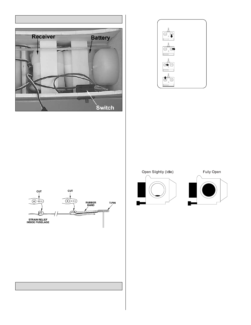
3. Hook up – following the manufacturer’s recommendations
– the receiver, switch harness and battery as shown in the
photo. At this time, it is suggested to allow the receiver and
battery the option of being moved until after the aircraft has
been balanced. Once balanced, the receiver and battery
must be secured into the aircraft to prevent them from
moving during flight. Once your model has been balance,
secure the location of the receiver and battery using the
wood supplied in the kit.
❏
4. Route the antenna to the tail of the model. You may
use your preferred method or the method we use in the
Great Planes model shop. Drill a 1/4" [6mm] hole through
the fuse side in the proximity of the receiver. Cut a 1/2"
[13mm] long piece of fuel tubing and install it in the hole.
Install a strain relief (as shown in the sketch), then route the
antenna through the fuel tubing to the bottom of the fuse at
the tail. Use a rubber band to attach the antenna to a T-pin
at the aft end of the fuselage. Do not cut or shorten the
antenna wire. Leave any excess to hang free.
❏
1. Turn on the transmitter and then the receiver. Standing
behind the plane, make the following movements with the
transmitter and observe the control surfaces:
If any of the servo movements are wrong, reverse the servo
direction with the servo reversing switches on the
transmitter.
❏
2. For added safety and convenience, the throttle should
be set up so the engine can be stopped using the throttle
trim. To do this, loosen the screw on the pushrod connector,
move the throttle pushrod so the carburetor is completely
closed with the throttle stick, and trim lever on the
transmitter fully back. (Note: If the carburetor does not fully
close, adjust the idle stop screw on the carburetor until it
will.) Next, tighten the screw on the pushrod connector. Test
the trim lever by advancing it to full. This will be a fast idle
position with the carburetor barrel open slightly (about
1/32" or .8mm).
Now move the throttle stick forward to full. Make sure the
carburetor barrel opens all the way. (See sketch.) If it
doesn’t open far enough or opens too far (bending the rod)
move the pushrod connector in or out on the servo arm
and/or the carburetor arm to gain or reduce movement.
Apply a small amount of thin CA onto the threads of the
pushrod connector. The throw will be correct when the
carburetor barrel will stop fully open at the same time the
throttle stick reaches full. With the throttle set up properly,
you should be able to run the engine with the trim lever set
midway to the full position (adjusted for a smooth but slow
idle). Then when it is time to stop the engine, simply pull back
the trim to close the carburetor and the engine will stop running.
❏
3. Check the movement of the control surfaces. Use a
ruler to match our measurements listed below. If your radio
features dual rates, set up both the high and low rates
following the radio system’s instructions. If your radio does
not have dual rates, set up the plane using low rates first
and increase the throws as you get familiar with the plane.
4-CHANNEL
TRANSMITTER
4-CHANNEL
TRANSMITTER
4-CHANNEL
TRANSMITTER
4-CHANNEL RADIO SET-UP
(STANDARD MODE 2)
TRANSMITTER
4-CHANNEL
ELEVATOR MOVES UP
RIGHT AILERON MOVES UP
LEFT AILERON MOVES DOWN
RUDDER MOVES RIGHT
CARBURETOR WIDE OPEN
Radio System Set-up
Battery & Receiver Installation
16