Radio installation – Great Planes Super Sportster 40 ARF - GPMA1040 User Manual
Page 14
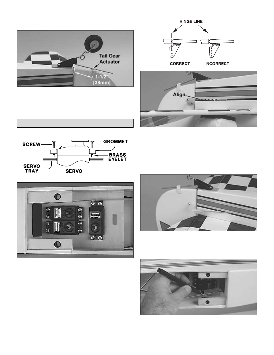
tail gear assembly to the plate using two #2 x 1/2" sheet
metal screws.
❏
3. Slide the tail gear actuator onto the tail gear wire. Mark
the location of the actuator on the rudder and remove the
covering inside those marks. Use 6-minute epoxy to attach
the actuator to the rudder.
❏
1. Mount the rudder, elevator and throttle servos in the fuselage.
Use the following sequence for mounting the servos into the
servo tray:
❏
A. Install rubber grommets and brass eyelets in the servos
using the provided sketch.
❏
B. Test fit the servos in the tray. Enlarge the openings if
needed to create a 1/32" [.8mm] gap around the servo.
❏
C. Mark servo mounting hole locations on the tray, then
drill 1/16" [1.5mm] pilot holes through each mark.
❏
D. Mount the servos with the screws provided with your
radio system.
❏
2. Install the rudder nylon control horn in line with the pushrod
exit. Hold the horn in position and mark the location of the
mounting holes. Drill 3/32" [2.5mm] mounting holes through
the marks. Wick two to three drops of thin CA into the holes
to harden the underlying balsa, and then re-drill the holes.
Attach the horn using two 2-56 x 5/8" machine screws and
a nylon nut plate. Do not overtighten the screws,
crushing the underlying balsa.
❏
3. Install the rudder pushrod. Place a clevis retainer onto a
clevis. Thread the clevis 14-turns onto the pushrod. Attach
the clevis to the outside hole on the control horn. Slightly
bend the pushrod as necessary to allow free movement.
❏
4. Center the rudder and rudder servo and mark the pushrod
where it crosses the servo arm. Enlarge the servo horn hole
with a 5/64" [2mm] drill bit. (The Hobbico Quick Drill set
(HCAR0699) works well for this purpose.)
Radio Installation
14