Great Planes Super Sportster 40 ARF - GPMA1040 User Manual
Page 15
❏
5. Make a 90º bend in the pushrod on your mark, then
insert it through the enlarged hole in the servo arm. Secure
the wire in place with a nylon FasLink. Trim the excess wire
1/16" [1.5mm] above the FasLink.
❏
6. Install the elevator control horn by positioning the horn
as close to the inboard edge of the elevator as possible and
mark the location of the mounting hole. Drill 3/32" [2.5mm]
mounting holes through the marks. Wick two to three drops
of thin CA into the holes to harden the underlying balsa, then
re-drill the holes. Attach the horns using two 2-56 x 5/8"
machine screws and a nylon nut plate. Do not overtighten
the screws, crushing the underlying balsa.
❏
7. Install the elevator pushrod. Place a clevis retainer onto
the clevis. Thread the clevis 14-turns onto the pushrod.
Attach the clevis to the outer hole of the control horn.
Slightly bend the pushrod wire as necessary to allow for free
movement.
❏
8. Center the elevator and elevator servo and mark the
pushrod where it crosses the servo arm. Enlarge the servo
horn hole with a 5/64" [2mm] drill bit.
❏
9. Make a 90º bend in the pushrod on your mark, then
insert it through the enlarged hole in the servo arm. Secure
the wire in place with a nylon FasLink. Trim the excess wire
1/16" [1.6mm] above the FasLink.
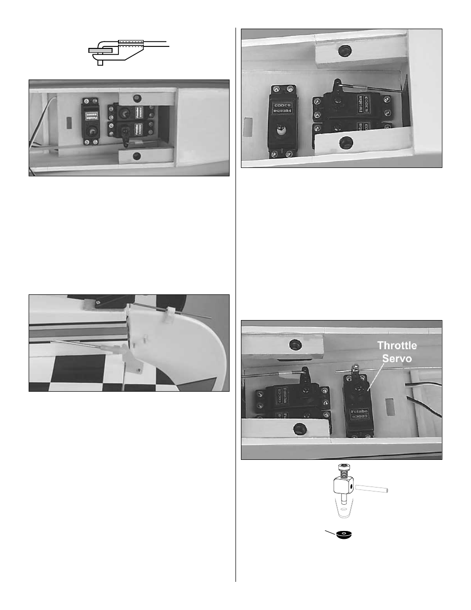
❏
10. Install a brass screw-lock pushrod connector with the
4-40 x 1/8" cap screw on the throttle servo horn. Snap the
nylon retainer onto the screw-lock pushrod connector post
beneath the servo horn.
RETAINER
15