Channel radio setup, Set the control throws, Balance the model (c.g.) – Great Planes Sequence F3A EP ARF - GPMA1575 User Manual
Page 20
20
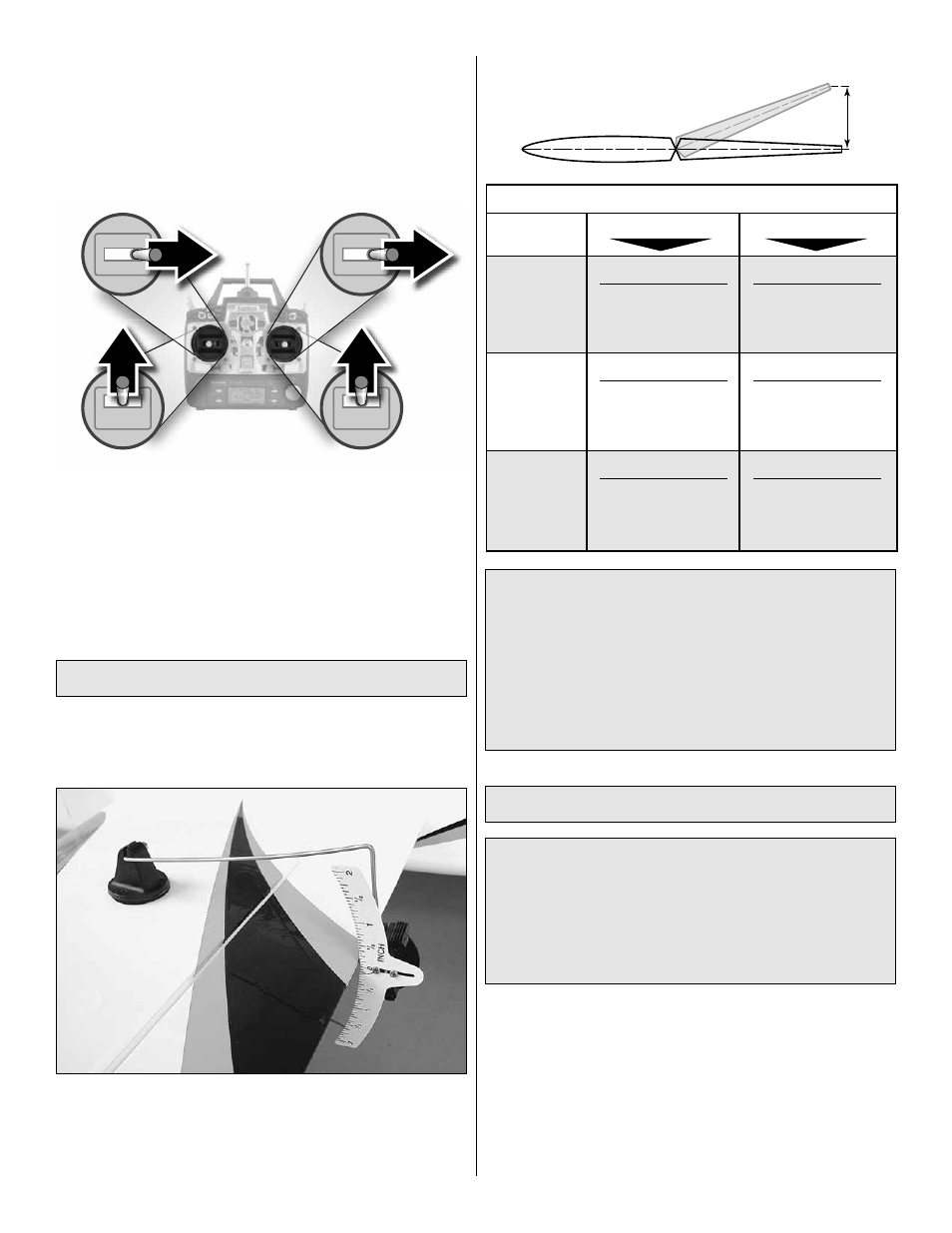
FULL
THROTTLE
RUDDER
MOVES
RIGHT
ELEVATOR
MOVES DOWN
RIGHT AILERON
MOVES UP
LEFT AILERON
MOVES DOWN
4-CHANNEL RADIO SETUP
(STANDARD MODE 2)
❏
3. Make certain that the control surfaces and the throttle
respond in the correct direction as shown in the diagram.
If any of the controls respond in the wrong direction, use
the servo reversing in the transmitter to reverse the servos
connected to those controls. Be certain the control surfaces
have remained centered. Adjust if necessary.
Set the Control Throws
Measure and set the low rate elevator throws and the high
and low rate throws for the rest of the control surfaces the
same way.
Use a Great Planes AccuThrow (or a ruler) to accurately
measure and set the control throw of each control surface
as indicated in the chart that follows. If your radio does not
have dual rates, we recommend setting the throws at the
low rate setting.
NOTE: The throws are measured at the widest part of the
elevators, rudder and ailerons.
These are the recommended control surface throws:
ELEVATOR
HIGH RATE
LOW RATE
3/8"
[9.5mm]
7 deg
Up
3/8"
[9.5mm]
7 deg
Down
1/4"
[6mm]
5 deg
Up
1/4"
[6mm]
5 deg
Down
RUDDER
2"
[51mm]
24 deg
Right
2"
[51mm]
24 deg
Left
1"
[25mm]
12 deg
Right
1"
[25mm]
12 deg
Left
AILERONS
3/4"
[19mm]
15 deg
Up
3/4"
[19mm]
15 deg
Down
1/2"
[13mm]
11 deg
Up
1/2"
[13mm]
11 deg
Down
IMPORTANT: The Sequence ARF has been extensively
fl own and tested to arrive at the throws at which it fl ies
best. Flying your model at these throws will provide you
with the greatest chance for successful fi rst fl ights. If, after
you have become accustomed to the way the Sequence
fl ies, you would like to change the throws to suit your taste,
that is fi ne. However, too much control throw could make
the model diffi cult to control, so remember, “more is not
always better.”
Balance the Model (C.G.)
More than any other factor, the C.G. (balance point) can
have the greatest effect on how a model fl ies, and may
determine whether or not your fi rst fl ight will be successful.
If you value this model and wish to enjoy it for many fl ights,
DO NOT OVERLOOK THIS IMPORTANT PROCEDURE.
A model that is not properly balanced will be unstable and
possibly unfl yable.
At this stage the model should be in ready-to-fl y condition
with all of the systems in place including the engine or
brushless motor, landing gear, and the radio system (and
battery pack if applicable).
❏
1. Use a felt-tip pen or 1/8" [3mm]-wide tape to accurately
mark the C.G. on the top of the wing on both sides of the
fuselage. The C.G. is located 4-7/8" [124mm] back from the
leading edge of the wing.