Great Planes Sequence F3A EP ARF - GPMA1575 User Manual
Page 14
14
the end of it. Insert the pushrod into the elevator exit slot and
attach the clevis to the outer hole of the elevator control horn.
With the elevators in the neutral position and the elevator
servo centered, mark the pushrod where it crosses the
middle hole of the elevator servo arm. Remove the pushrod,
make a 90 degree bend at your mark, cut off of the excess
pushrod 1/4" [6mm] beyond the bend and attach the pushrod
to the servo arm using a FasLink pushrod connector.
❏
6. Install the rudder servo in the center of the servo
mounting rails with the servo spline facing the front of
the plane.
❏
7. Cut two arms from a four-armed servo arm, leaving
two arms opposite each other in place. Center the servo and
install the servo arm perpendicular to the servo case.
❏
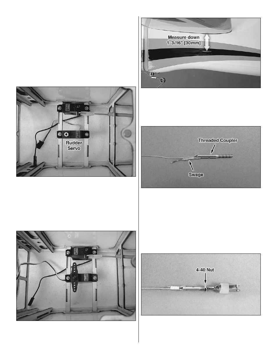
8. Trim the covering from the rudder pull-pull cable exit
slots on each side of the fuselage. The slots may be diffi cult
to fi nd underneath the covering. Measure down 1-3/16"
[30mm] from the underside of the stab in the location shown
for the position of the slots.
❏
9. Cut the provided pull-pull string accurately in half. Apply
a drop of thin CA to each 1/4" [6mm] end of both pieces
of string. Allow the CA to harden and use a sharp hobby
knife to trim away the frayed ends of the strings. Feed one
end of each string through a brass threaded coupler. Slide a
swage (crimp) onto each string and loop the end that you put
through the threaded coupler back through the swage. Slide
the swage to the base of the threaded coupler and use a pair
of large pliers to crimp the swage onto the string. Confi rm
that the string is adequately secure in the swage.
❏
10. Thread a 4-40 nut with threadlocking compound
onto the threaded couplers. Thread a 4-40 threaded metal
clevis after each nut. Slide a silicone clevis retainer over
the clevises.