Install the tail servos and pushrods – Great Planes Sequence F3A EP ARF - GPMA1575 User Manual
Page 12
12
❏
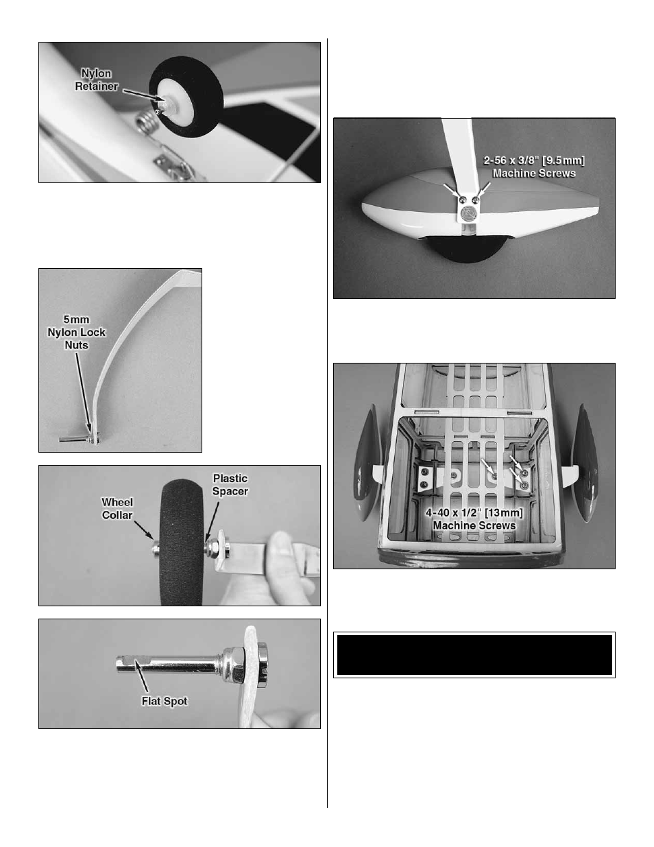
6. Install the tail wheel onto the wire and secure it in place
with a nylon retainer. Confi rm that the tail wheel rotates
freely. Oil the axle and adjust the position of the retainer if
necessary. A drop of CA on the retainer will ensure that it will
not come loose from the wire.
❏
7. Secure the main
axles to the landing
gear legs using the
5mm nylon lock nuts.
❏
8. Slide a 5/32" [4mm] plastic spacer onto each axle
followed by a 2-1/2" [64mm] wheel and then a 5/32" [4mm]
wheel collar. Mark the location of the threaded holes in the
wheel collars onto the axles. Use a fi le or rotary tool such as
a Dremel to grind fl at spots at the marks on the axles.
❏
9. Reinstall the spacers, wheel collars and wheels onto
the axles. Thread a 6-32 set screw into each wheel collar
and tighten the screws against the fl at spots on the axles. Be
sure that the wheel rotates freely on the axle. Oil the axles
if necessary.
❏
10. Attach the wheel pants to the landing gear legs using
four 2-56 x 3/8" [9.5mm] machine screws, four #2 fl at washers,
four #2 lock washers, and thread locking compound.
❏
11. Attach the landing gear legs to the fuselage using six
4-40 x 1/2" [13mm] machine screws, six #4 fl at washers, six
#4 lock washers, and thread locking compound.
INSTALL THE TAIL SERVOS
AND PUSHRODS
The tail servos can be installed in either the forward or aft
position for balancing purposes. If using the recommended
equipment, you will want to install the servos in the forward
position. If you plan to use a motor and/or battery that is
heavier than our recommended setup, you may wish to install
the tail servos in the aft position to minimize or eliminate any
additional tail ballast that would be needed to balance the
plane at our recommended C.G. For aft servo installation
directions, look ahead to the end of this section.