Great Planes Sequence F3A EP ARF - GPMA1575 User Manual
Page 10
10
❏
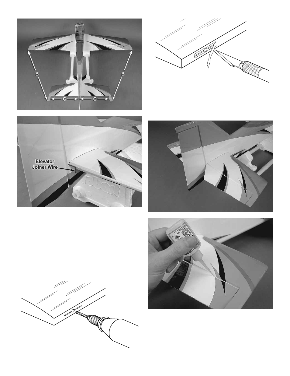
3. Insert the elevator joiner wire into the aft end of the
stab slot. Coat the exposed wood on the top and bottom of
the stab with 30-minute epoxy as well as the mating edges of
the stab slot. Insert the stab into the slot and center it left and
right. Measure from the wing tips to the stab tips and make
those distances equal. Wipe away excess epoxy with paper
towels dampened with denatured alcohol. Confi rm that the
stab and wing are still parallel. A weight can be added to
one side of the stab to make any small corrections. Allow the
epoxy to cure undisturbed. The wing can now be removed
from the fuselage and set aside.
Drill a 3/32" [2.4mm] hole
1/2" [13mm] deep, in the center
of the hinge slot.
Cut the covering
away from the slot.
❏
4. Drill a 3/32" [2.4mm] hole 1/2" [13mm] deep into the
center of each hinge slot in the elevator halves and stab.
Trim the covering away from each hinge slot to ensure that
the hinges will be properly glued in place.
❏
5. Test fi t the elevator halves onto the stab with CA hinges.
If necessary, enlarge the hinge slots with a hobby knife.
When satisfi ed with the fi t, insert a CA hinge halfway into
each hinge slot in the stab. Push a pin through the middle of
each hinge to keep them centered. The elevator joiner wire
ends fi t into the pre-drilled holes and slots at the LE of the
elevators. When satisfi ed, roughen the ends of the elevator