Great Planes RV-4 60 ARF - GPMA1357 User Manual
Page 20
❏
19. On the threaded end of the wire thread a 4-40 nut and
the clevis onto the wire. Slide a clevis keeper over the clevis.
Center the rudder servo and the rudder. Adjust the clevis as
needed until the clevis pin is aligned with the hole in the
control horn. Attach the clevis to the control horn. Then
tighten the 4-40 nut against the clevis. Apply a drop of
threadlocker to the nut before tightening it against the clevis.
Slide the clevis keeper over the clevis.
❏
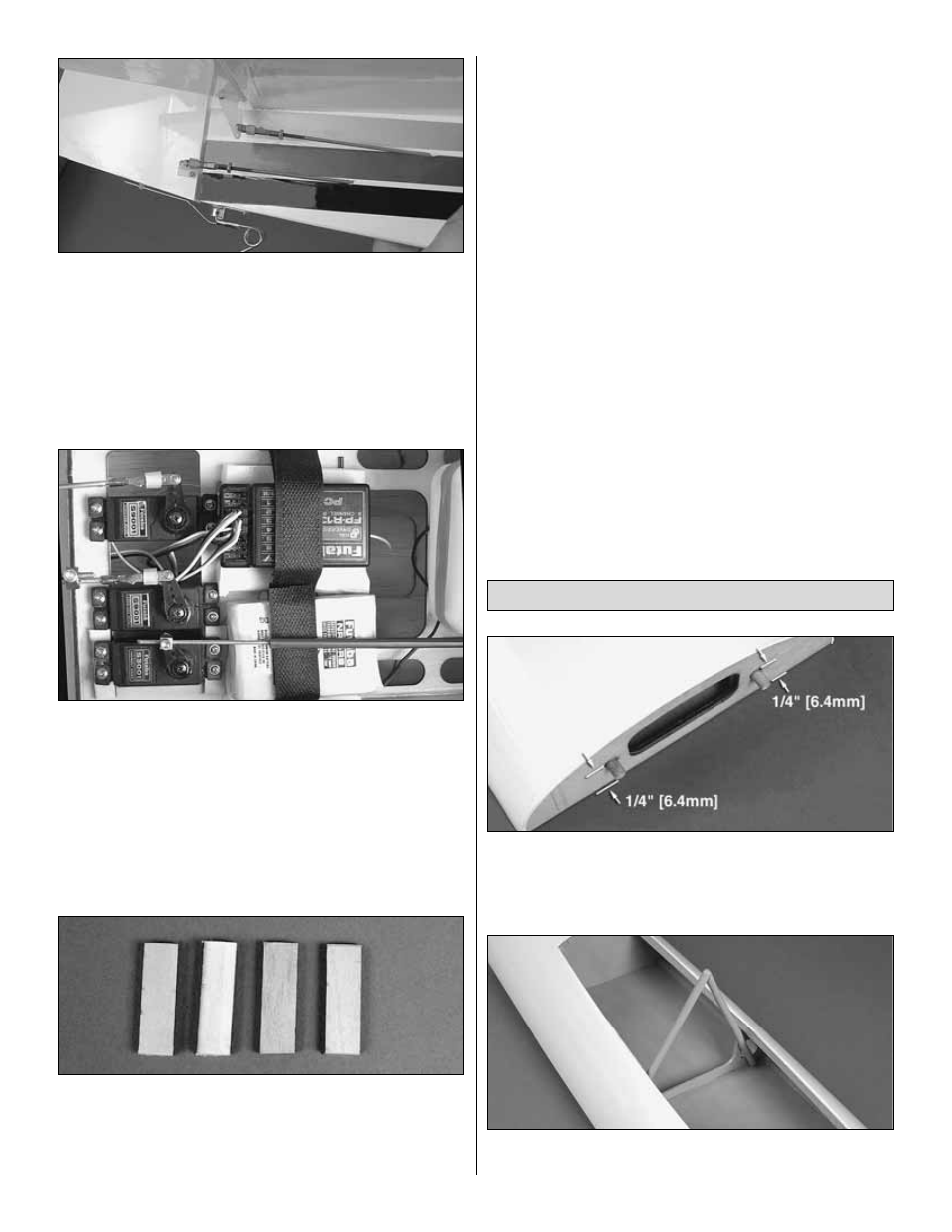
20. Install a strip of Velcro through the slots in the servo
tray to hold the receiver in place. Place the receiver on 1/4"
[6mm] foam. Tighten the Velcro around the receiver.
❏
21. Route the antenna wire into the antenna tube in the
bottom of the fuselage. The antenna tube is longer than the
receiver antenna; the antenna will not exit the fuselage.
Once the antenna is fully installed in the antenna tube, apply
a small piece of tape to the antenna and tube to keep the
antenna from sliding out of the antenna tube.
❏
22. Place the battery on a piece of 1/4" [6mm] foam and
strap it in place with Velcro. If the receiver battery does not
fit under the throttle linkage, raise the throttle servo by gluing
1/8" x 5/16" x 3/4" [3 x 8 x 19mm] plywood spacers under
the servo. Then re-mount the servo.
❏
23. Install a switch harness and charge jack to the
fuselage. Connect the switch to the battery. Be sure to use
heat-shrink tubing or tape to be sure the battery to switch
connection is secure.
❏
24. Plug the servos into the receiver following the
instructions that came with your radio system. Make
adjustments to the position of the servo arms as needed.
❏
1. Locate and glue the two 1/4" x 5/8" [6 x 16mm] dowels
into the front of the canopy base. When properly installed
approximately 1/4" [6mm] of the dowel will extend from the
front of the canopy base.
❏
2. Locate and glue the turn-over post to the front side of
the middle former.
Assemble the Canopy
20