Assemble the fuselage – Great Planes RV-4 60 ARF - GPMA1357 User Manual
Page 10
❏ ❏
14. Locate a .074" x 6" [.074" x 152mm] pushrod wire
threaded on one end. Screw a nylon clevis onto the
threaded end of the wire 20 full turns. Install a silicone clevis
keeper onto the clevis. Then, install the clevis in the second
hole from the end of the flap control horn. Center the flap
and align the wire pushrod with the hole in the end of the
servo arm. Using a marker, mark the location where the wire
aligns with the hole in the servo arm. On that mark make a
90° bend. From the bend, measure an additional 3/16"
[4.8mm]. Then, cut off the excess pushrod wire. Install the
wire into the hole in the servo arm using a nylon FasLink.
❏ ❏
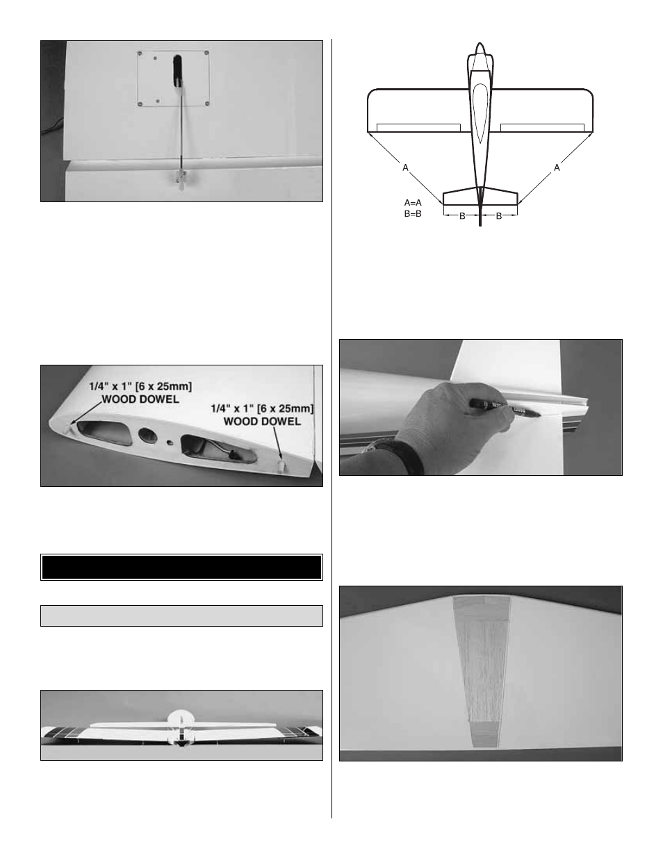
15. Locate two 1/4" x 1" [6 x 25mm] wood dowels. Glue
them into the holes as shown.
❏
16. Repeat steps 1 to 15 for the left wing.
❏
1. Install the aluminum wing joiner tube into the hole in
the fuselage. Slide the wing panels onto the tube, sliding the
wing panels against the fuselage.
❏
2. Test fit the stab into the opening in the back of the
fuselage. Stand back and look at the stab in relation to the
wing. The stab should be parallel with the wing. If not, sand
the stab saddle until the stab and wing are aligned.
❏
2. Measure the distance from the tip of the stab to the tip of
each wing. Adjust the position of the stab until both are equal.
❏
3. Using a fine-tip marker, trace the outline of the fuselage
onto the top and bottom of the stab.
❏
4. Remove the stab from the fuselage. Use a sharp #11
blade or the expert tip that follows to cut the covering inside
the lines you have drawn. Use caution not to cut through the
surface of the wing skin. Remove the covering.
Install the Stab, Elevators & Rudder
ASSEMBLE THE FUSELAGE
10