Great Planes Reactor 1.60 ARF - GPMA1580 User Manual
Page 32
32
❏
9. Wrap your receiver and battery pack with 1/4" [6.4mm]
thick latex foam. Use the straps you made to mount your
battery and receiver to the center equipment tray.
❏
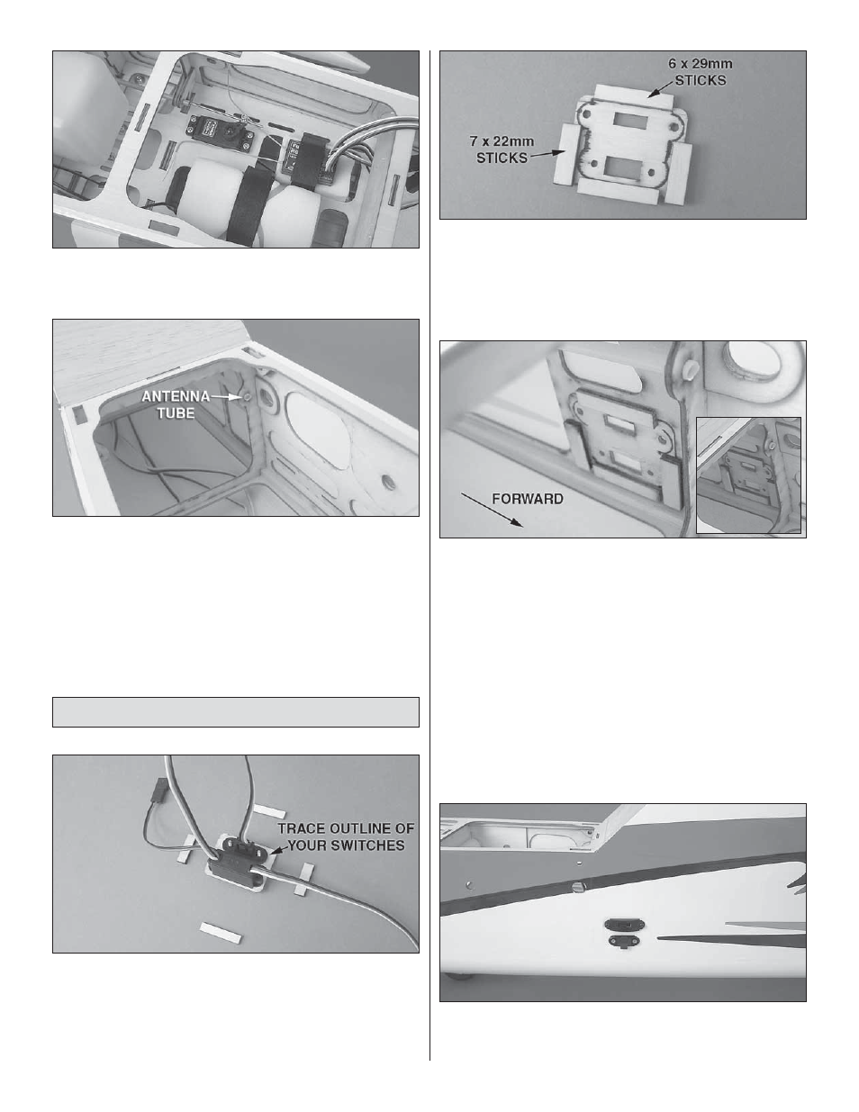
10. We used a 2.4GHz radio system for this build-up, but if
you’re using a 72MHz radio system, an antenna routing tube
is provided for you in the upper left side of the fuselage.
Skip to the “Final Assembly” section.
Radio System Installation – Electric Brushless
❏
1. Locate the switch plate that fi ts your brand of radio switch.
Four plates are supplied: two Futaba switch & Ernst charge
jacks and two Hobbico heavy-duty & Ernst charge jacks. Fit
your switch and charge jack to the plate and use a pen or
pencil to draw an outline of the switch and jack onto the back
side of the plate. Remove the switch and charge jack.
❏
2. Use two 7 x 22mm and two 6 x 29mm sticks to make a
fl ange for the charge plate.
❏
3. Install the switch plate on the model using epoxy. For
C.G. reasons, the radio equipment is mounted in the aft
equipment bay. A cutout for the switch plate is provided in the
left and right rear fuselage. You may choose either location.
❏
4. Tack down the covering over the switch plate using a
covering iron set to a low temperature.
❏
5. Trim the covering from over the switch plate holes and
install the switch and charge jack. Iron the covering to the
switch plate before you begin trimming.