Great Planes Reactor 1.60 ARF - GPMA1580 User Manual
Page 31
31
Radio System Installation – Glow Engine
❏
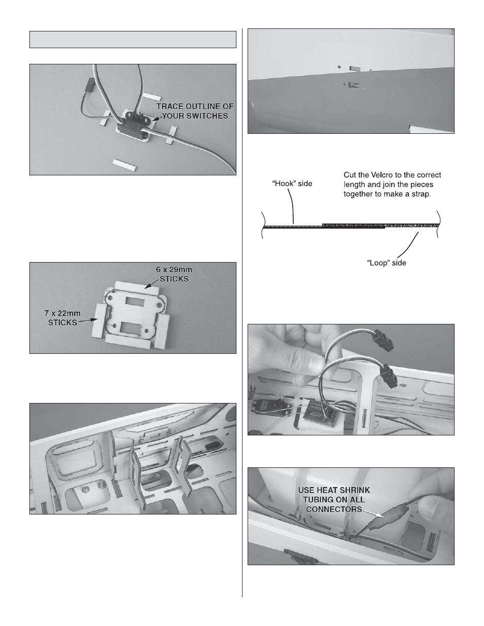
1. Locate the switch plate that fi ts your brand of radio switch.
Four plates are supplied: two Futaba switch & Ernst charge
jacks and two Hobbico heavy-duty & Ernst charge jacks. Fit
your switch and charge jack to the plate and use a pen or
pencil to draw an outline of the switch and jack onto the back
side of the plate. Remove the switch and charge jack.
❏
2. Use two 7 x 22mm and two 6 x 29mm sticks to make a
fl ange for the charge plate.
❏
3. Install the switch plate on the model using epoxy to
attach it. There are six places to mount the switch plate, so
choose the one that suits you best.
❏
4. Tack down the covering over the switch plate using a
covering iron set to a low temperature.
❏
5. Trim the covering from over the switch plate holes and
install the switch and charge jack.
❏
6. Locate the non-adhesive backed hook and loop
material. Make two sets of straps for your receiver and
battery by joining a piece of “hook” material to a piece of
“loop” material.
❏
7. Connect a Y-connector to each aileron channel. Connect
the other servo leads to your receiver
❏
8. Connect the battery to the switch and the switch to
the radio. Use heat shrink tubing to secure the connection
between the battery and the switch.