Great Planes G-44 Widgeon Seaplane EP ARF - GPMA1151 User Manual
Page 9
9
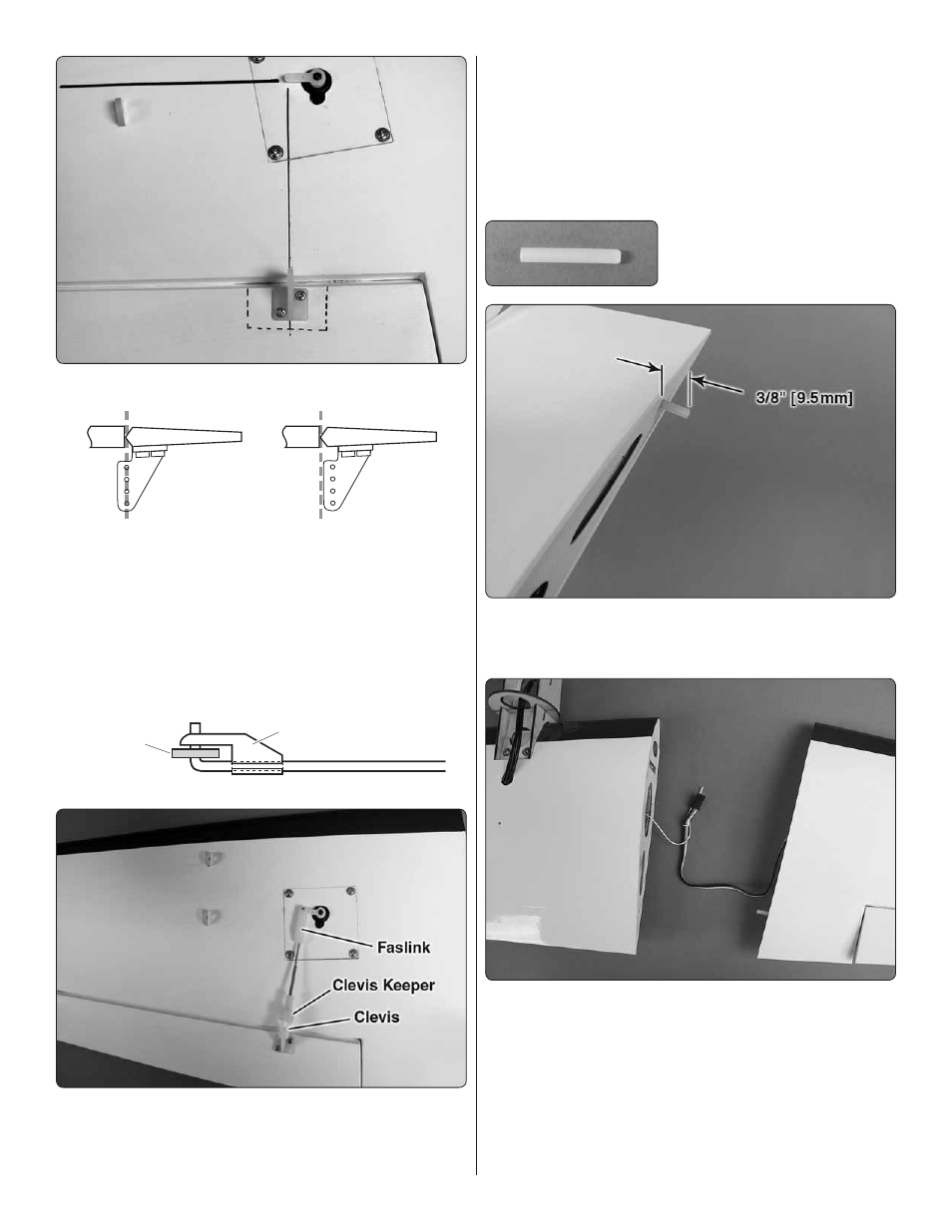
Hinge Line
Hinge Line
Correct
Incorrect
Place the aileron control horn on the hardwood plate in line
with the servo arm. Drill a 1/16" [1.6mm] hole through each
of the mounting holes, drilling into the hardwood plate.
DO
Not
drill through the top of the aileron! Secure the control
horn with two 5/64" x 3/8" [2mm x 9.5mm] screws. Remove
the screws and add a couple of drops of thin CA glue to the
holes to harden the threads. After the glue has dried secure
the horn to the aileron.
FasLink
Servo Horn
Pushrod Wire
❏ ❏
9. Thread a nylon clevis 20 turns onto a 4-1/4" [110mm]
pushrod. Slide a silicone clevis retainer onto each clevis and
connect the clevis in the hole, one hole in from the end of the
nylon control horn
❏ ❏
10. Use tape to hold the ailerons in the neutral position.
Make a mark on the pushrods where they cross the outer
holes in the servo arms. Make a 90 degree bend at the mark
on the pushrods and cut off the excess pushrod 1/4" [5mm]
beyond the bend. Attach the pushrods to the servo arms using
nylon Faslinks. Thread the clevis up or down on the pushrod
as necessary to center the aileron. When satisfi ed, slide the
silicone clevis retainer to the end of the clevis to secure it.
❏❏
11. Locate one of the 1/8" x
3/4" [3mm x 19mm] nylon dowels.
Test fi t it into the hole located at the trailing edge of the root
rib. Glue the dowel into the hole leaving 3/8" [9.5mm] of the
pin extending from the root rib.
❏ ❏
12. Attached at the root rib of the wing center section
is a string that runs out through the wing out the hole on the
bottom center of the wing. Tie the string to the servo lead of
the outer wing panel.