Balance the model (c.g.) – Great Planes G-44 Widgeon Seaplane EP ARF - GPMA1151 User Manual
Page 21
21
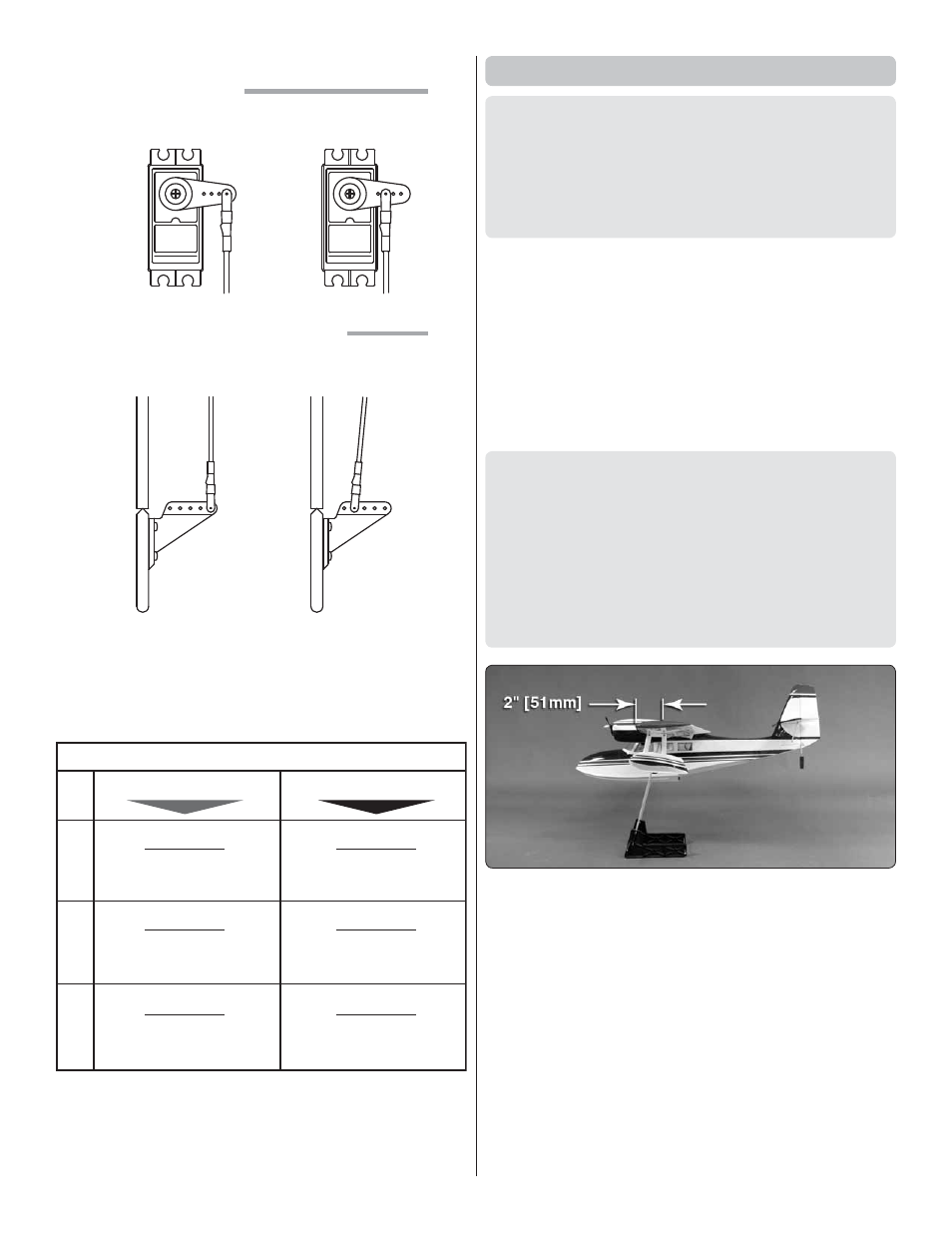
The pushrod farther out
means
More Throw
The pushrod closer in
means
Less Throw
The pushrod farther out
means
Less Throw
The pushrod closer in
means
More Throw
At the Servos
At the Control Surfaces
❏
4. If necessary, adjust the location of the pushrod on the
servo arm or on the elevator horn, or program the ATVs in
your transmitter to increase or decrease the throw according
to the measurements in the control throws chart.
These are the recommended control surface throws:
ELEV
A
TOR
R
UDDER
AILER
ONS
LOW RATE
1/4"
[6 mm] 6°
Up & Down
3/8"
[10 mm] 12°
Up & Down
5/8"
[ 16 mm] 12°
Right & Left
HIGH RATE
3/8"
[10 mm] 8°
Up & Down
1/2"
[13 mm] 17°
Up & Down
1"
[ 25mm] 19°
Right & Left
If your radio does not have dual rates, we recommend setting
the throws at the low rate settings.
NOTE
: The throws are measured at the
widest part
of the
elevators, rudder and ailerons.
Balance the Model (C.G.)
More than any other factor, the C.G. (center of gravity/
balance point) can have the greatest effect on how a model
fl ies and could determine whether or not your fi rst fl ight will
be successful. If you value your model and wish to enjoy it
for many fl ights,
DO NOT OVERLOOK THIS IMPORTANT
PROCEDURE.
A model that is not properly balanced may
be unstable and possibly unfl yable.
At this stage the model should be in ready-to-fl y condition with
all
of the components in place including the complete radio
system, motors, battery, propeller, spinner and pilot.
❏
1. If using a Great Planes C.G. Machine,
™
set the rulers to
2" [51mm]. If not using a C.G. Machine, use a fi ne-point felt
tip pen to mark lines on the bottom of the wing on both sides
of the fuselage 2" [51mm] back from the leading edge. Apply
narrow (1/16" [2mm]) strips of tape over the lines so you will
be able to feel them when lifting the model with your fi ngers.
This is where your model should balance for the fi rst
fl ights. Later, you may experiment by shifting the C.G. 1/4"
[6mm] forward or 1/4" [6mm] back to change the fl ying
characteristics. Moving the C.G. forward will improve the
smoothness and stability, but the model will then be less
aerobatic (which may be fi ne for less-experienced pilots).
Moving the C.G. aft makes the model more maneuverable
and aerobatic for experienced pilots. In any case,
start at
the recommended balance point
and do not at any time
balance the model outside the specifi ed range.
❏
2. With the wing attached to the fuselage, all parts of the
model installed (ready to fl y) and an empty fuel tank, place the
model on a Great Planes CG Machine, or lift it at the balance
point you marked.
❏
3. If the tail drops, the model is “tail heavy.” If possible,
move the battery pack and/or receiver forward to get the
model to balance. If the nose drops, the model is “nose heavy.”
If possible, move the battery pack and/or receiver aft. If the
receiver and/or battery cannot be moved, or if additional weight
is still required, nose weight may be easily added by using
Great Planes “stick-on” lead (GPMQ4485) and installing it as
far forward in the nose of the fuselage as possible. To fi nd out
how much weight is required, place incrementally increasing
amounts of weight on the top of the fuselage over the location
where it would be mounted inside until the model balances.