Install the propeller, Balance the model (c.g.) – Great Planes Cosmic Wind EP ARF - GPMA1810 User Manual
Page 15
15
distance the elevator moves up from center is the “up” elevator
throw. Measure the down elevator throw the same way.
❏
4. Measure and set the
low rate
elevator throws and the
high and low rate throws for the rest of the control surfaces
the same way.
If your radio does not have dual rates, we recommend setting
the throws at the high rate settings.
NOTE
: The throws are measured at the
widest part
of the
elevators, rudder and ailerons.
These are the recommended control surface throws:
ELEV
A
TOR
R
UDDER
AILER
ONS
LOW RATE
1/8"
[3 mm] 4°
Up & Down
1/8"
[ 3 mm] 7°
Up & Down
3/8"
[10 mm] 10°
Right & Left
HIGH RATE
1/4"
[ 6 mm] 8°
Up & Down
3 /16"
[5 mm] 11°
Up & Down
9/16"
[ 14 mm] 14°
Right & Left
CAUTION:
The throws appear to be small. However, the
model has been extensively fl own and tested to arrive at the
throws at which it fl ies best. Flying your model at these throws
will provide you with the greatest chance for successful fi rst
fl ights. Increasing the throws can cause the plane to be very
diffi cult to fl y.
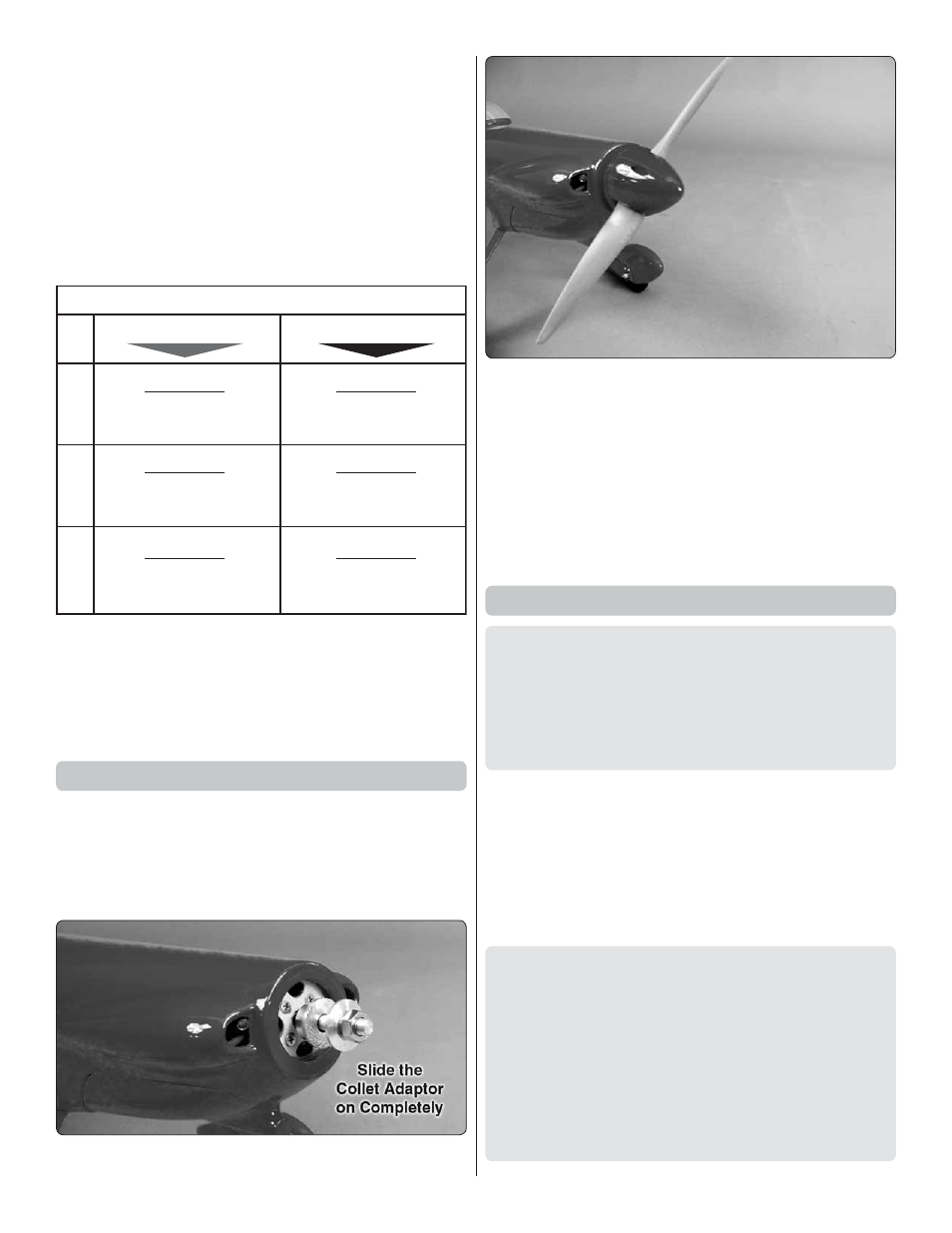
Install the Propeller
Insert the motor battery in the fuselage. Switch on the
transmitter and connect the motor battery to the ESC. While
securely holding the plane, slowly advance the throttle. The
motor should rotate counterclockwise when viewed from the
front. If it rotates the wrong direction, switch two of the three
motor wires.
❏
1. Slide the collet type prop adapter on the motor shaft.
❏
2. Use a prop reamer or drill bit to enlarge the
spinner back
plate
to fi t your motor’s prop adapter. Install the spinner back
plate, propeller with washer and prop nut and the
spinner
cone
. Secure the spinner cone to the back plate with two
2.5
× 7 mm Sheet metal screws
.
❏
3. Insert a fl ight battery in the fuselage and use the hook and
loop material to hold the battery in position.
Do not connect
the battery to the ESC while balancing the model.
❏
4. Install the battery hatch cover.
Balance the Model (C.G.)
More than any other factor, the
C.G.
(balance point) can
have the
greatest
effect on how a model fl ies, and may
determine whether or not your fi rst fl ight will be successful.
If you value this model and wish to enjoy it for many fl ights,
DO NOT OVERLOOK THIS IMPORTANT PROCEDURE.
A model that is not properly balanced will be unstable and
possibly unfl yable.
At this stage the model should be in ready-to-fl y condition
with all of the systems in place including the motor, landing
gear, battery and the radio system.
❏
1. Use a felt-tip pen or 1/8" [3 mm]-wide tape to accurately
mark the C.G. on the top of the wing at the side of the fuselage.
The C.G. is located 2–1/16" [52 mm] back from the leading
edge of the wing at the side of the fuselage.
This is where your model should balance for the fi rst fl ights.
Later, you may wish to experiment by shifting the C.G. up
to 3/16" [4.5 mm] forward or 3/16" [4.5 mm] back to change
the fl ying characteristics. Moving the C.G. forward may
improve the smoothness and stability, but the model may
then require more speed for takeoff and make it more diffi cult
to slow for landing. Moving the C.G. aft makes the model
more maneuverable, but could also cause it to become too
diffi cult to control. In any case,
start at the recommended
balance point
and do not at any time balance the model
outside the specifi ed range.