Set the control throws – Great Planes 25% Pitts M-12S 50cc ARF - GPMA1421 User Manual
Page 34
34
Set the Control Throws
To ensure a successful fi rst fl ight, set up your Pitts M-12s
according to the control throws specifi ed in this manual.
The throws have been determined through actual fl ight
testing and accurate record-keeping, allowing the model
to perform in the manner in which it was intended. If, after
you have become accustomed to the way the Pitts M-12s
fl ies, you would like to change the throws to suit your
taste, that is fi ne. However, too much control throw could
make the model too responsive and diffi cult to control, so
remember, “more is not always better.”
❏
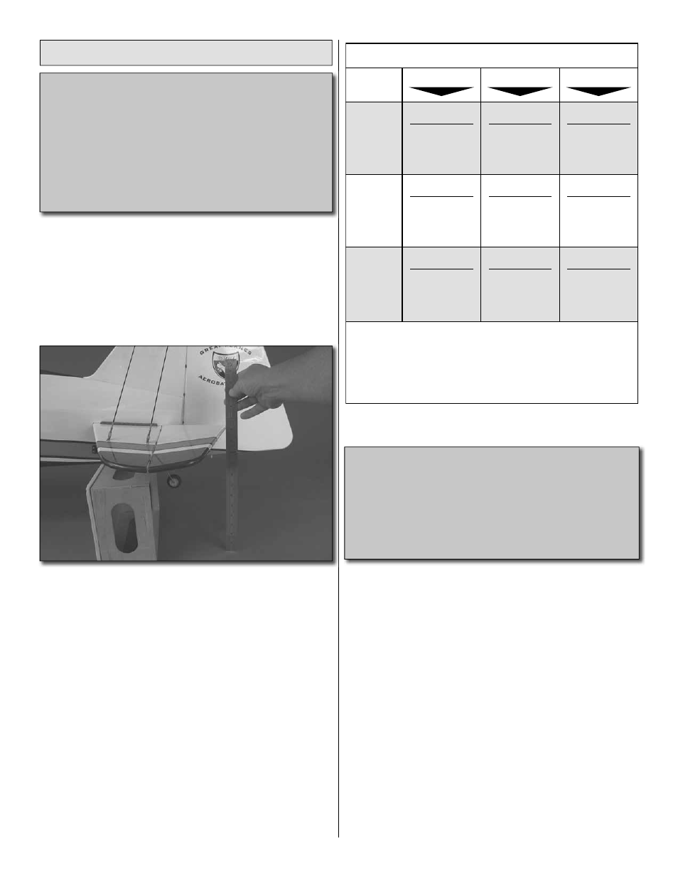
1. Use a box or something similar to prop up the bottom
of the fuselage so the horizontal stabilizer and wing will be
level.
Measure the high rate elevator throw fi rst…
❏
2. Hold a ruler vertically on your workbench against the
widest part (front to back) of the trailing edge of the elevator.
Note the measurement on the ruler.
❏
3. Move the elevator up with your transmitter and move the
ruler forward so it will remain contacting the trailing edge. The
distance the elevator moves up from center is the “up” elevator
throw. Measure the down elevator throw the same way.
❏
4. Referring to the Proper Pushrod Hookup illustrations
on the opposite page, adjust the location of the pushrod
on the servo arm or on the elevator horn and program the
ATVs in your transmitter to increase or decrease the throw
according to the measurements in the control throws chart.
❏
5. Measure and set the low rate elevator throws and the
high and low rate throws for the rest of the control surfaces
the same way.
NOTE: The throws are measured at the widest part of the
elevators, rudder and ailerons.
These are the recommended control surface throws:
ELEVATOR
LOW RATE
RUDDER
AILERONS
1"
[25
mm
]
10°
Up
1"
[25
mm
]
10°
Down
2"
[51
mm
]
10°
Right
2"
[51
mm
]
10°
Left
3/4"
[19
mm
]
12°
Up
3/4"
[19
mm
]
12°
Down
3D RATE
2-7/8"
[73
mm
]
29°
Up
2-7/8"
[73
mm
]
29°
Down
6"
[152
mm
]
30°
Right
6"
[152
mm
]
30°
Left
2"
[51
mm
]
33°
Up
2"
[51
mm
]
33°
Down
HIGH RATE
1-1/4"
[32
mm
]
12°
Up
1-1/4"
[32
mm
]
12°
Down
3"
[76
mm
]
14°
Right
3"
[76
mm
]
14°
Left
1"
[25
mm
]
16°
Up
1"
[25
mm
]
16°
Down
Note: The use of exponential will make the plane less sensitive at the center of
the control gimbals on the radio. We programmed -40% exponential on our
Futaba radios. Check your manufacturer’s instructions for exponential settings.
You may need to program positive exponential instead of negative exponential
as is done for Futaba radios.
In addition to exponential we found a 13% rudder to aileron mix helped to
minimize roll coupling in knife edge flight.
The following are general guidelines for hooking up
pushrods to the control surface and the servo. The
installation method used throughout this manual
provided safe, effective control and allows you to
achieve all of the required control throws. If for some
reason you have decided to hook up the controls
differently than we outlined, please review the following
to assure you have a safe set up.