Install the engine and throttle servo – Great Planes 25% Pitts M-12S 50cc ARF - GPMA1421 User Manual
Page 22
22
❏
9. Install the rudder servo into the rear servo opening in
the center of the fuselage with the hardware that came with
your servo. Install a 2.5" [64mm] double servo arm onto the
servo (GPMM1600) and then center the servo.
❏
10. Slide the wire cable with the swivel ball link into
the hole in the fuselage until all of the wire is inside of the
fuselage. Attach the nylon swivel ball link to the outer hole in
the control horn the same as was done for the elevators.
❏
11. Drill the outer holes of the servo arm to 1/8" [3.2mm].
Install a swivel ball link to both ends of the arm. Attach a
brass crimp connector and a threaded brass coupler to
each of the wires using the same technique used for the
connections to the rudder. (Adjust the wire until both wires
are tight before crimping the connector to the wire). Cut off
any excess wire. If the wire is not tight enough, adjust the
tension by turning the swivel ball link further in or out on the
threaded brass couplers.
Install the Engine and Throttle Servo
The instructions we have included for engine mounting
are for the Desert Aircraft DA-50 rear carb engine with 3"
[76mm] stand-offs. If you will be mounting a different brand
of engine you will have to modify your installation as needed
to accommodate your engine. Whether you will be installing a
DA-50 or another brand of engine, it is recommended you take
a few minutes to read these instructions prior to beginning
the installation so you can be familiar with the process we
recommend. We understand that “large scale” modelers have
many different preferences for hardware and methods for
installation. We have provided what we believe is a simple and
reliable installation. Feel free to substitute different hardware
or use other installation methods you may prefer.
❏
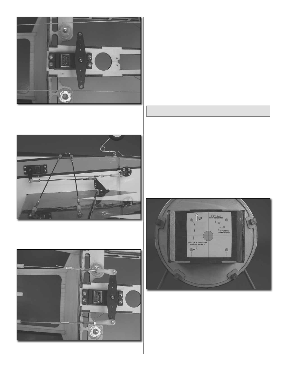
1. Cut out the engine mounting pattern located on the
back cover of this manual. Tape the pattern in place, aligning
it with the reference lines etched into the fi rewall. Notice the
pattern has an arrow on it that references “UP”. The arrow
should be pointed towards the top of the fuselage. This
pattern will provide the proper mounting holes for an inverted
engine installation.
❏
2. On each of the reference marks drill a 5/64" [2mm] pilot
hole. With your pilot hole as a reference, drill each hole the
size indicated on the pattern.