Balance the model (c.g.) – Great Planes F1 Rocket Evo GP/EP ARF - GPMA1030 User Manual
Page 24
24
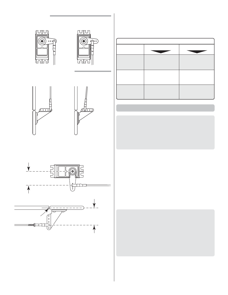
The pushrod farther out
means More Throw
The pushrod closer in
means Less Throw
The pushrod farther out
means Less Throw
The pushrod closer in
means More Throw
At the Servos
At the Control Surfaces
❏
3. If necessary, adjust the location of the pushrod on the
servo arm or on the elevator horn, or program the ATVs in
your transmitter to increase or decrease the throw according
to the measurements in the control throws chart.
SERVO ARM
OFFSET
Pivot point
CONTROL
HORN OFFSET
❏
4. When connecting pushrods and setting up your control
throws, it is critically important to use proper pushrod
geometry—that is the distance from the pushrod on the
servo arm to the center of the output shaft (servo arm offset)
compared to the distance from the pushrod on the control
horn to the pivot point (control horn offset).
❏
5. Measure and set the low rate elevator throws and the
high and low rate throws for the rest of the control surfaces
the same way.
If your radio does not have dual rates, we recommend setting
the throws at the low rate settings.
NOTE: The throws are measured at the widest part of the
elevators, rudder and ailerons.
These are the recommended control surface throws:
ELEVATOR
HIGH
LOW
7/8"
[22 mm]
20°
1/2"
[13 mm]
12°
7/16"
[11mm]
20°
1/4"
[ 6 mm]
12°
1-1/2"
[ 38 mm]
24°
1"
[25 mm]
15°
RUDDER
AILERONS
Up & Down
Up & Down
Right & Left
Balance the Model (C.G.)
More than any other factor, the C.G. (center of gravity/
balance point) can have the greatest effect on how a model
fl ies and could determine whether or not your fi rst fl ight will
be successful. If you value your model and wish to enjoy it
for many fl ights, DO NOT OVERLOOK THIS IMPORTANT
PROCEDURE. A model that is not properly balanced may
be unstable and possibly unfl yable.
At this stage the model should be in ready-to-fl y condition
with all of the components in place including the complete
radio system, engine, muffl er, propeller, spinner and pilot. If
you’ve built the electric version, install the motor battery. If
you’ve built the glow version the fuel tank should be empty.
❏
1. If using a Great Planes C.G. Machine, set the rulers to 3
-1/4" [83 mm]. If not using a C.G. Machine, use a fi ne-point felt
tip pen to mark lines on the top of wing on both sides of the
fuselage 3 -1/4" [ 83 mm] back from the leading edge. Apply
narrow (1/16" [ 2 mm]) strips of tape over the lines so you will
be able to feel them when lifting the model with your fi ngers.
This is where your model should balance for the fi rst
fl ights. Later, you may experiment by shifting the C.G. 1/2"
[13 mm] forward or 7/16" [11mm] back to change the fl ying
characteristics. Moving the C.G. forward will improve the
smoothness and stability, but the model will then be less
aerobatic (which may be fi ne for less-experienced pilots).
Moving the C.G. aft makes the model more maneuverable
and aerobatic for experienced pilots. In any case, start at
the recommended balance point and do not at any time
balance the model outside the specifi ed range.