Set the control throws – Great Planes Citabria EP ARF - GPMA1127 User Manual
Page 15
15
❏
4. Apply the remaining hook and loop material to the bottom
of the horizontal fuselage at the approximate location for the
motor battery. Attach an opposite piece of hook and loop
material to the battery. Trial fi t the motor battery to the bottom
of the fuselage and recheck the C.G.
GET THE MODEL READY TO FLY
Check the Control Directions
❏
1. Remove the propeller and switch on the
transmitter and connect the motor battery. Check
all the control surfaces to see if they are centered.
FULL
THROTTLE
RUDDER
MOVES
RIGHT
ELEVATOR
MOVES DOWN
RIGHT AILERON
MOVES UP
LEFT AILERON
MOVES DOWN
4-CHANNEL RADIO SET UP
(STANDARD MODE 2)
❏
2. Make certain that the control surfaces respond in the
correct direction as shown in the diagram. If any of the controls
respond in the wrong direction, use the servo reversing in the
transmitter to reverse the servos connected to those controls.
Be certain the control surfaces have remained centered. Adjust
if necessary.
Set the Control Throws
To ensure a successful fi rst fl ight, set up your Citabria 3D
according to the control throws specifi ed in this manual.
The throws have been determined through actual fl ight
testing and accurate record-keeping, allowing the model
to perform in the manner in which it was intended. If, after
you have become accustomed to the way the Citabria
3D fl ies, you would like to change the throws to suit your
taste, that is fi ne. However, too much control throw could
make the model too responsive and diffi cult to control, so
remember, “more is not always better.”
❏
1. Use a box or something similar to prop up the bottom
of the fuselage so the horizontal stabilizer and wing will
be level.
❏
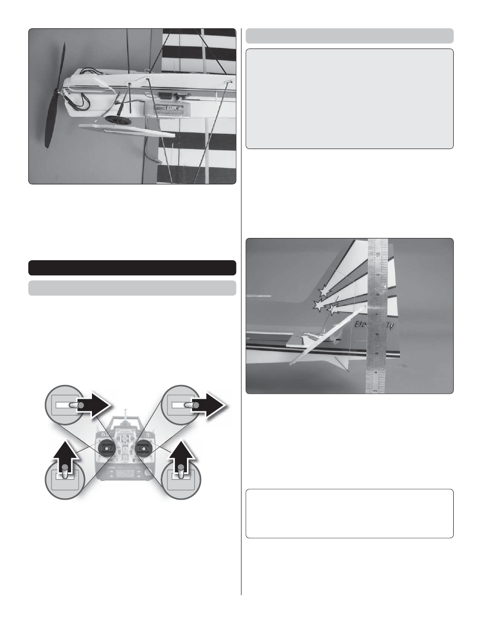
2. Measure the 3D elevator throw fi rst. Hold a ruler vertically
on your workbench against the widest part (front to back) of
the trailing edge of the elevator. Note the measurement on
the ruler.
❏
3. Move the elevator up with your transmitter and move
the ruler forward so it will remain contacting the trailing
edge. The distance the elevator moves up from center is
the “up” elevator throw. Measure the down elevator throw
the same way.
❏
4. Measure and set the
high and low rate
elevator throws
and the high, low, and 3D rate throws for the rest of the control
surfaces the same way.
If your radio does not have dual rates, we recommend
setting the throws at the high rate settings.
NOTE
: The throws are measured at the
widest part
of
the elevators, rudder and ailerons.