Great Planes RimFire 42mm Power System User Manual
Page 2
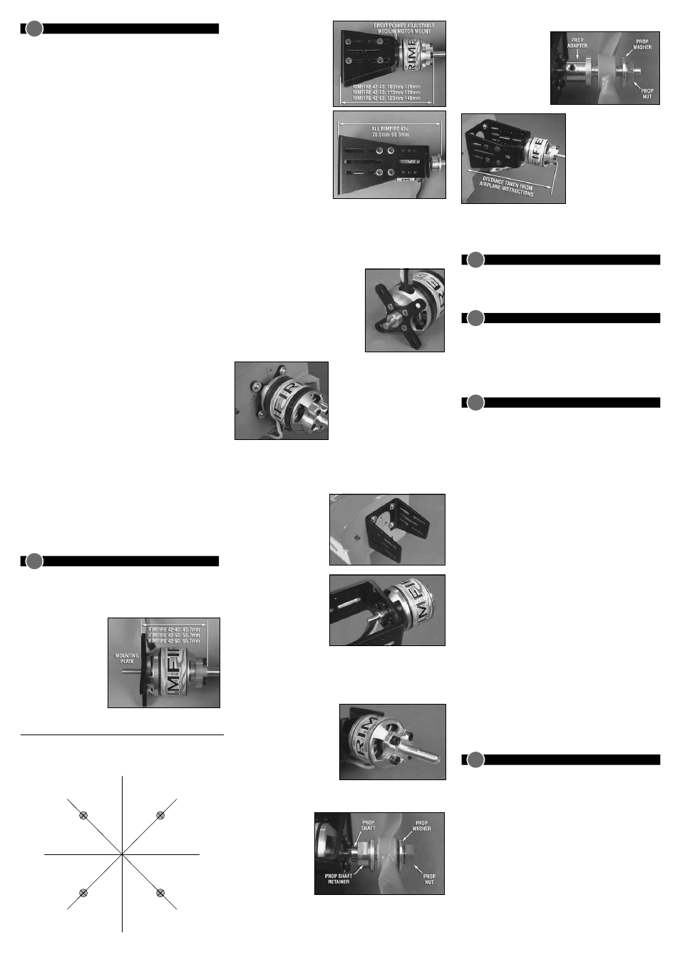
SET SCREW TYPE PROP ADAPTER INSTALLATION
Slide the prop adapter over
the output shaft of the gear
drive or motor. Apply a drop
of Great Planes Threadlocker
(GPMR6060) to the set
screws and install them in the
prop adapter, tightening them
against the motor shaft.
Position the motor/front plate
assembly between the backplate.
Measure the distance from the
firewall to the front of the prop
adapter. Attach the front plate of
the motor mount to the back
plate using the eight 6-32x1/2”
SHC screws, eight #6 flat
washers and four aluminum
screw plates, spaced out as far
as possible.
Note: Once the motor is mounted in position, the collet type prop
adapter can be removed to allow the cowl to be mounted. This adapter
is easily installed with the cowl already installed.
9
INSTALL THE BRUSHLESS ESC
Mount your ESC in the desired location. Always make sure that the
ESC is positioned so that it gets some cooling air flowing over it. Use
the instructions included with the ESC to correctly connect the ESC.
10
RIMFIRE MOTOR MAINTENANCE
RimFire brushless motors require virtually no maintenance. There are
no brushes to wear out and replace. The precision bearings have a
very long service life and should last a very long time. The internal
parts of the motor should not require any cleaning. The only thing that
needs to be checked is to make sure all the screws and set screws
remain tight.
11
IMPORTANT PRECAUTIONS
•
Once the battery is connected to the ESC, stay clear of the motor
and prop.
•
DO NOT apply an input voltage that exceeds the maximum
specification of each motor.
•
DO NOT apply currents to the motor that exceed the maximum
specifications of each motor.
•
DO NOT allow the input connectors to accidentally touch each other
while power is applied to the motor. Make sure all input connections
are insulated electrically.
•
DO NOT allow water or moisture to enter the motor, as it can
cause permanent damage to the motor and possibly short out the
attached ESC.
•
DO NOT cut the coated wires from the motor. If you must remove
the bullet connectors, unsolder them.
•
Allow the motor to cool after each flight.
•
The motor shaft of the motor will rotate at very high rpm. DO NOT
attempt to touch the shaft while it is rotating. If setting up the
motor/ESC on the workbench, make sure the motor is securely
attached and that nothing is attached to the motor shaft BEFORE
applying power.
•
Never attempt to use a damaged motor (having mechanical or
electrical defects).
ElectriFly carries a complete line of Ammo (inrunner style) and
RimFire (outrunner style) brushless motors, gear drives, motor
mounts, prop adapters and speed controls. For a complete list of
these products, check out our web site at:
www.greatplanes.com
www.electrifly.com
or visit your nearest hobby shop that carries the full line of Great
Planes and ElectriFly products.
12
REPLACEMENT PARTS
GPMM3114 4mm Gold Plated Bullet Connectors - Male (3)
GPMM3115 4mm Gold Plated Bullet Connectors - Female (3)
GPMQ4906
RimFire Prop Adapter for 42mm Motors
GPMG1205
RimFire Backplate Motor Mount for 35-42mm Motors
GPMG1434
C-Clip (10) for 5mm RimFire Motor Shafts
GPMG1456
Bearings (3) for RimFire 42-xx-xx Motors
GPMG1412
Replacement Shaft Kit for RimFire 42-40-xx Motors
GPMG1414
Replacement Shaft Kit for RimFire 42-50-xx Motors
GPMG1416
Replacement Shaft Kit for RimFire 42-60-xx Motors
Check the airplane instruction
manual for the correct distance.
These pictures show the distances
from the firewall to the front of
the prop adapter using the
different mounting systems.
If you are replacing a glow engine
with an electric motor system,
remove the nylon engine mount
and replace it with the Medium
Motor Mount or RimFire mounting
plate, using the same bolts to
attach it to the firewall. If the
firewall has not been drilled for an
engine mount and blind nuts, use
the mounting template on the
header card to locate the mounting
holes. Drill the four mounting
holes and install 6-32 blind nuts
from the back of the firewall.
MOUNTING PLATE INSTALLATION
If attaching the motor to the firewall using the adjustable motor mount,
skip to the Medium Motor Mount Installation.
Note: Apply a drop of Threadlocker (GPMR6060) to all bolts and screws
used to install the motor on the plane.
Attach the backplate to the motor using four
3x8mm flat head machine screws and
threadlocking compound.
Attach the Backplate of the motor mount
to the firewall using four 6-32 machine
screws and four #6 flat washers. Apply
a drop of Great Planes Threadlocker to
the screws before installing them.
Mount the aluminum prop adapter to
the motor case using four 3x7mm SHC
screws. Apply a drop of threadlocker to
the threads of each bolt.
MEDIUM MOTOR MOUNT INSTALLATION
Note: Apply a drop of Threadlocker (GPMR6060) to all bolts and screws
used to install the motor on the plane.
Attach the backplate of the
motor mount to the firewall
using four 6-32 machine screws
and four #6 flat washers.
Remove the c-clip from the
motor shaft. Mount the RimFire
motor to the motor mount front
plate (front or back) using four
3mm machine screws.
Install the collet or set screw
prop adapter on the motor shaft
or the aluminum prop adapter on the motor case. The RimFire 42mm
motors use the 5mm prop adapter (GPMQ4966 Collet Type or GPMQ4939
Set Screw Type).
ALUMINUM PROP ADAPTER INCLUDED WITH MOTOR
Mount the aluminum prop adapter
to the motor case using four
3x7mm SHC screws and
threadlocking compound.
COLLET TYPE PROP ADAPTER INSTALLATION
Slide the prop shaft over
the output shaft of the gear
drive or motor. Next slide
the prop shaft retainer over
the prop shaft. Note that
the hole through the
retainer is tapered. Make
sure that the side with the
larger diameter hole is
installed first. Install the
spinner backplate (if used, not included), the prop, prop washer and then
the prop nut. Tighten the prop nut against the prop. This will cause the
tapered hole in the prop shaft retainer to squeeze the prop shaft around
the output shaft. Carefully pull on the prop to make sure it is securely
attached to the output shaft of the gear drive.
7
DETERMINE WHAT YOU NEED TO BUILD YOUR POWER SYSTEM
Now that you have one component for your power system, there
are several different ways to select the rest. In time, experience will
help you to determine what works best for you, but an easy way to
determine what you need now is the following.
Procedure #1: If you know the size of the propeller you want to turn
and the rpm, then:
❏
1. Find the combination that delivers the closest performance to what
you want (refer to the ElectriFly web site for typical combinations),
or refer to the airplane manufacturer’s recommendations.
❏
2. Note the recommended battery voltage.
❏
3. Determine the battery capacity needed based on the current draw
of your system and your desired fl ight time.
❏
4. Determine the ESC you need based on the system current draw.
See the ESC section.
Procedure #2: If you know the approximate weight of your airplane,
including the motor and battery, and the performance you want from
it, answer the questions below to determine the correct power system
for your plane. You may need to make more than one calculation using
different motors and battery combinations. See the battery section for
some of the battery weights for the suggested batteries.
❏
1.
Perform the following calculation to determine the wattage
required:
• If you expect trainer-like performance, then multiply
75 x Airplane Weight (lbs)
• If you expect aerobatic or high speed-like performance, then
multiply 100 x Airplane Weight (lbs)
• If you expect 3D or extreme performance, multiply
150 x Airplane Weight (lbs)
❏
2. The number you get is the minimum wattage you will need for
your plane to perform as you wish. Watts = current (A) × voltage
(V). Using suggested power system combinations as reference,
determine what combination gives you the performance you
want based on wattage and maximum propeller size that will fi t
on the plane.
❏
3. Choose a battery voltage within the recommended range of the
motor.
❏
4. Determine the battery capacity needed based on the current draw
of your system and your desired fl ight time.
❏
5. Determine the ESC you need based on the system current draw.
In addition to these two procedures, you can also visit the Great
Planes ElectriFly web site for descriptions of the power systems
recommended for our line of electric and glow airplanes as well as
more detailed explanation on the subject.
Recommended Setups:
RimFire .25: 3S Battery, 11x8.5 Electric Prop
RimFire .32: 4S Battery, 13x8 Electric Prop
RimFire .46: 6S Battery, 11x5.5 Electric Prop
RimFire .55: 6S Battery, 13x10 Electric Prop
8
ASSEMBLE YOUR POWER SYSTEM
Once the required RimFire motor has been determined, it needs to be
installed on the plane. To determine the best mounting system, the
distance from the firewall to the front of the prop adapter first needs to
be determined.
It can be mounted directly to
the firewall using the RimFire
aluminum mounting plate
(included with the motor). or
an ElectriFly Medium Motor
Mount (GPMG1255). Both
mounting systems are direct
replacements for the Great
Planes
®
.20-.48 and .40-.70
nylon engine mounts.
RimFire 42mm Aluminum Mounting Plate
Template
Entire Contents © 2009
GPMZ0029Instr for 42mm RimFire