Great Planes CG Machine - GPMR2400 User Manual
Page 2
Y
our C
.G.
Machine is no
w ready to use
.
B
ALANCE Y
OUR
MODEL
T
o
balance y
our airplane at a predetermined location:
1.
Adjust the width of the bases so the upr
ight rods clear the sides of
the fuselage and landing gear
.
2.
Deter
mine the distance from the leading edge of the wing to the
balance point, from y
our air
plane’
s plans or instr
uctions
.
3.
Slide the r
ulers to the distance deter
mined in the pre
vious step
.
Vie
w the measurement in the center of the r
uler holder windo
ws
.
Note:
F
or maxim
um stability
, balance high-wing air
planes r
ight side
up and lo
w-wing air
planes upside do
wn.
4.
Place y
our air
plane in an appro
ximately le
v
el attitude on the f
oam
ru
b
ber pads
.
Piv
ot the r
ulers until the
y are hor
iz
ontal.
Hold y
our
air
plane as y
ou mo
v
e
it f
orw
ard until the leading edge of the wing
contacts the pointers
.
This is the position at which y
our model should
be balanced.
Note:
In some cases
, especially with high-wing tail dr
aggers
, the
landing gear ma
y interf
ere with the upr
ight rods
.
If that is the case
,
tur
n
the C
.G.
Machine 180° and s
witch the soc
k
et cap and r
uler
assemb
lies
.
If this does not w
o
rk, r
aise the front or bac
k of the bases
to change the angle of the upr
ight rods in relation to y
our air
plane
, b
u
t
not enough to mak
e the bases unstab
le
.
Note:
If
, f
or some reason, y
ou need to spread the bases more than
12" apar
t, y
ou ma
y do so b
y
substituting longer 3/16" base joiner rods
.
5.
Gently release the air
plane
...If the tail drops
, the model is
tail hea
vy
and y
ou m
ust either add w
eight to the nose or mo
v
e
inter
nal
components (batter
y,
ser
v
o
s
, etc.) f
orw
ard.
If the nose drops
, the
model is
nose hea
vy
and y
ou m
ust either add w
eight to the tail or
mo
v
e
inter
nal components aft.
See
General Balancing
Tips
.
T
o
measure where y
our airplane currentl
y balances:
1.
Slide the r
ulers out near the 7-inch line
.
2.
P
osition y
our air
plane on the f
oam pads so it rests le
v
el.
3.
Piv
ot the r
ulers so the
y are hor
iz
ontal, then adjust the r
ulers until
the pointers touch the leading edge of the wing.
4.
Read the distance in both r
uler holder windo
ws
.
Note:
If the tw
o
distances diff
er slightly
, it is sufficiently accur
ate to use the
a
v
er
age
of
the tw
o v
alues
.
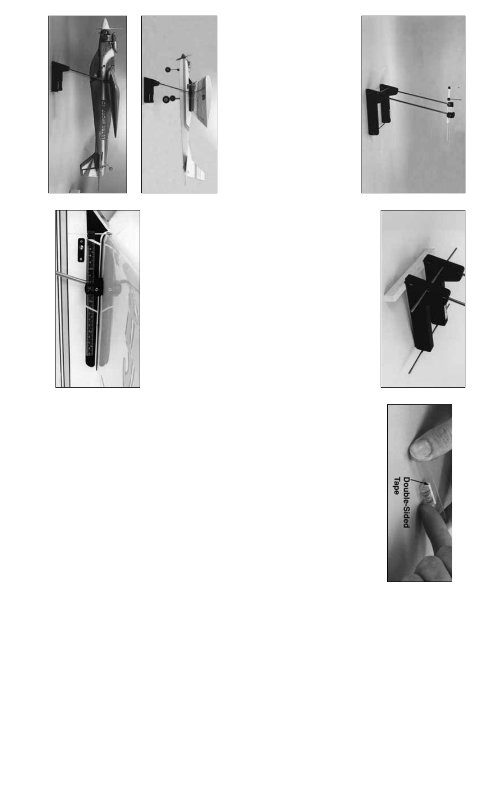
HO
W T
O
USE THE
LEVEL
T
o
assist y
ou in accur
ately balancing y
our air
planes
, w
e
ha
v
e
included
a
small, lightw
eight le
v
el vial.
Y
ou can use this in v
a
rious w
a
ys to help
deter
mine when y
our air
plane is tr
uly le
v
el, r
ather than relying on
estimation.
Although the le
v
el vial ma
y be used alone
, y
ou ma
y attach
it to the 1/2" x 3" plastic str
ip
, with a small piece of doub
le-sided tape
(cut from the included 1" square), carefully aligning the vial with one
edge of the str
ip
.
Attaching the vial to the plastic str
ip will allo
w it to be
taped to the side of the fuselage along a ref
erence line
.Y
ou can also
place the assemb
led le
v
el on the stabiliz
er
.
GENERAL B
ALANCING
TIPS
A.
Alw
a
ys balance y
our air
plane in a ready-to-fly condition with an
empty fuel tank (unless the fuel tank is
behind
the C
.G.).
Chec
k y
our
air
plane’
s instr
uction man
ual f
or specific balancing instr
uctions
.
B
.
On models where the leading edge of the wing s
w
eeps rearw
ard,
the distance betw
een the leading edge and the C
.G.
decreases along
the span.
In other w
ords
, the leading edge of the wing gets closer to
the C
.G.
to
w
ard the wing tip
.
The C
.G.
sho
wn on most plans is where
the wing meets the fuselage
.
This means the distance betw
een the
leading edge of the wing and the C
.G.
is v
alid
onl
y
ne
xt to the
fuselage;
so
, f
or tapered wings
, y
ou should position the upr
ight rods
and the f
oam pads as close to the fuselage as possib
le
.
C
.
Bef
ore y
ou add w
eight to balance y
our model, if possib
le
, rearr
ange
the inter
nal components
.
Add w
eight only if y
ou m
ust.
D
.
If y
ou m
ust add nose w
eight, star
t with a Great Planes 1 oz.
or
2 oz.
spinner w
eight (a w
eight that fits inside y
our spinner
, and tak
es
the place of the prop w
asher), as this places the w
eight f
ar f
orw
ard
where it has the most eff
ect.
If y
our plane does not ha
v
e
a spinner
,
then use a Great Planes hea
vy br
ass prop n
ut.
If this does not pro
vide
enough w
eight to balance
, add Great Planes stic
k-on lead w
eight to
the front of the model on the front or bac
k of the fire
w
all or another
location that will not interf
ere with other systems
.
N
e
v
er mount
w
eights to the co
wl of y
our model because it is not meant to suppor
t
additional w
eight.
E.
Stic
k-on lead w
eight w
o
rks w
ell f
or tail w
eight too
.Y
ou can stic
k the
w
eights directly to the co
v
e
ring, or cut an access hatch in the fuselage
and install the w
eights inside
, then reinstall the hatch.
Bef
ore y
ou cut
the model open to install w
eights inside
, y
ou should first confir
m the
amount of tail w
eight y
ou require b
y
test flying y
our model with the
w
eight stuc
k to the outside
.
Bef
ore y
ou per
manently stic
k w
eights to
the co
v
e
ring, remo
v
e
all residual e
xhaust or other oil.
P
o
k
e
a f
e
w
pinholes through the co
v
e
ring in the area where y
ou will place the
w
eight and apply a drop of thin CA to each pinhole to mak
e sure the
co
v
e
ring is securely bonded to the str
ucture (and the w
eight securely
bonded to the model).
Attach the stic
k-on lead w
eight to the bottom of
the stab or fuse
.
F.
F
or the first flights it is common to balance the air
plane at or
slightl
y
forw
ard of the
center
of the recommended balance r
ange
.
F
or first flights it is desir
ab
le to ha
v
e
a model that is stab
le
.
G.
In addition to chec
king the C
.G., y
ou should also balance
y
our model
later
ally
(from side to side).
Lift y
our model se
v
e
ral times b
y
the
propeller and the v
e
rtical fin.
This ma
y require a helper if y
ou ha
v
e
a
large model.
Add w
eight to the wing tip opposite the hea
vy side of the
model until it balances
.
TR
OUBLESHOO
TING C.G.
PR
OBLEMS
Y
our model ma
y be nose hea
vy if:
Y
ou cannot lift the nose on final approach and it seems to o
v
ershoot
landings
, or landing speeds are too high, or the model requires lots of
forw
ard stic
k (do
wn ele
v
ator) to hold it le
v
el while in
v
e
rted, or y
our
aerobatic model will not snap roll or gener
ally seems to be too stab
le
.
Y
our model ma
y be tail hea
vy if:
It seems unstab
le or o
v
erreacts to control inputs
, or the tail drops
while in a high bank
ed tur
n, or no f
orw
ard stic
k (do
wn ele
v
ator) is
required to maintain le
v
el flight while the model is in
v
e
rted
(although
neutr
ally stab
le models such as contempor
ar
y patter
n planes require
vir
tually no do
wn ele
v
ator to maintain in
v
e
rted flight),
or if upon
landing approach y
our model flares without adding an
y up ele
v
ator
, or
upon landing do
wn ele
v
ator is required to pre
v
ent a stall.
A
CCESSORIES
Here are some order n
umbers f
or Great Planes Accessor
ies:
Great Planes Stic
k-on Lead
W
eight (GPMQ4485)
Great Planes 1/4-28 Br
ass Spinner Nut 2.5 oz.
(GPMQ4640)
Great Planes 1 oz.
Spinner
W
eight (GPMQ4645)
Great Planes 2 oz.
Spinner
W
eight (GPMQ4646)
W
e
hope y
ou enjo
y y
our Great Planes C
.G.
Machine and ha
v
e
an
easier time of balancing y
our ne
xt model and can impro
v
e
the flight
char
acter
istics of y
our current models
.
PAR
TS LIST
P
a
rt
#
.......................Qty
...........................................Description
NYLON141
................2
........................................................Base
NYLON138
................2
.............................................Soc
k
et Cap
NYLON139
................2
.............................................Rule Holder
NYLON140
................2
.........................................Rule End Cap
LEVEL01
...................1
.................................................Le
v
el Vial
LEVEL02
...................1
..............................1/2" x 3" Plastic Str
ip
WBNT262
..................2
.............................Leading Edge P
ointer
SCR
W072
..................2
..........................2-56
Threaded Ball Link
FT
AP001
....................1
......................1" x 1" Doub
le-Sided
T
ape
FO
AM002
..................2
..................Self-Stic
k F
oam Rub
ber P
a
d
SCR
W043
..................2
..................#4 x 3/8" Sheet Metal Scre
w
NYLON142
................1
........................................Rule Set (L&R)
R
OD003
.....................2
............................1/4" x 16" Upr
ight Rod
WIRES07
...................2
.............................3/16" x 12" Base Rod
STKER46
..................1
..............................C
.G.
Machine Stic
k
e
r
Pr
inted In USA
3059256