GME TX3200 User Manual
Page 11
11
2. Gently press the rubber strain relief into the
hole surrounding the socket so that the slot
around the strain relief fits neatly inside the
lip of the hole.
Removing the Microphone
1. Squeeze the rubber strain relief near the
front panel to disengage the slot, and slide
the strain relief back along the microphone
cord.
2. Squeeze the plastic tab on the microphone
plug towards the plug to unlock it while
gently pulling the plug outwards. If the plug
does not come out easily, the tab has not
released correctly and should be squeezed
again.
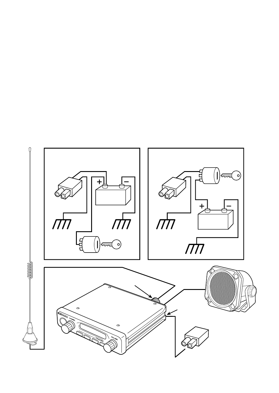
DC POWER CONNECTION
The TX3200 is designed for 13.8 Volt DC,
negative earth installations only (i.e. where the
negative terminal of the battery is connected to
the chassis or frame of the vehicle).
There are two recommended methods of
installation.
Radio remains on when the ignition switch
is off:
Connect the radio’s negative (black) lead to the
vehicle’s chassis, or if preferred, directly to the
battery’s negative terminal.
The radio’s positive (red) lead should be
connected directly to the battery’s positive
Coax Cable
Connector Plug
DC Socket
UHF Aerial
Extension
Speaker
Antenna Socket
Ignition Switch
RED
BLACK
Chassis
Radio remains on when the ignition
switch is off
Car Battery
Connector
Plug
Chassis
Ignition Switch
RED
BLACK
Chassis
Radio turns on and off with the
ignition switch
Connector
Plug
Chassis
Car Battery