Garelick 79715 3.5 GAS RISE COMMANDER SEAT User Manual
Page 2
Installation and Operation Instructions –
Commander Series Seat Hardware
Form 12.489
SWIVEL FRICTION ADJUSTMENT:
There are six adjusting screws to minimize seat swivel wobble. To
adjust, loosen Jam Nut using a 1/4” Allen Wrench. Turn screw until it
stops. Do not over tighten; light pressure is sufficient. Repeat for all six
screws. Check seat for ease of rotation. If seat is difficult to rotate, then
back screw off slightly and reset all Jam Nuts.
REMOVAL OF GAS SPRING:
Refer to Fig. 1.
1. Fully extend gas spring by pulling the cam lock handle out and
pulling the height adjustment lever UP. The seat will rise. Push the
cam lock handle in.
2. Remove seat from seat slide by removing 4 screws.
3. Remove slide assembly from detachable seat base plate by
removing [6] 3/8-16x1” socket head cap screws [A].
Refer to Fig. 2.
4. Remove slide top plate by unscrewing [8] 1/4-20x3/4” flathead
allen bolts [B].
5. Remove release bar guide by unscrewing [2] 1/4-20x1”
flathead allen screws [G], rotate height adjustment lever to
expose jam nut [C] located on gas spring shaft.
6. Remove 17mm jam nut [C].
NOTE: If jam nut and 3” swivel nut rotate in unison, tighten jam
nut so it will snug up the swivel. Then back off nut.
Refer to Fig. 3.
7. Tip unit on its side.
8. Remove cylinder mounting bracket by unscrewing [2] 1/4-
20x1” flathead allen screws [D]. Unscrew gas spring assembly
by rotating it counterclockwise from the threaded end. Pull out
gas spring assembly.
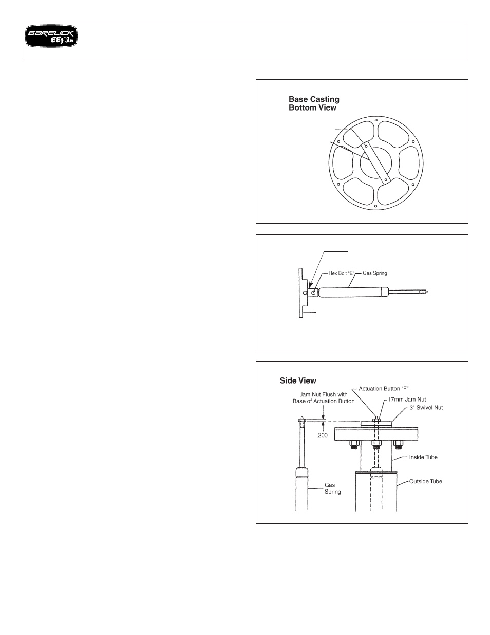
Refer to Fig. 4.
9. Detach clevis or cylinder mounting bracket (depending on which
gas spring you have) from gas spring by removing hex bolt (E).
INSTALLATION OF GAS SPRING:
1. Attach gas spring to clevis or cylinder mounting bracket with hex
bolt.
Refer to Fig. 5.
2. Thread gas spring assembly into swivel nut so that the threads
are exposed approximately .2”. Thread jam nut onto gas spring
shaft until the top of the jam nut is flush with the base of the
actuation button [F].
3. Align cylinder mounting bracket and secure with [2] 1/4-20x1”
flathead allen screws.
4. Snug jam nut against 3” swivel nut. Rotate height adjustment
lever until centered over gas spring actuation button.
5. Check unit for proper function using height adjustment lever.
Make sure unit will lock at intermediate heights, if not readjust
cylinder.
6. Attach release bar guide with [2] 1/4-20x1” flathead allen
screws.
7. Replace the seat slide top plate and secure it in place with [8]
1/4-20x3/4” flathead allen screws.
8. Mount slide assembly on detachable seat base and secure with
[6] 3/8-16x1” socket head cap screws.
9. Reattach the seat.
FOR SPARE PARTS, PLEASE CALL CUSTOMER SERVICE
FIG. 4
FIG. 5
FIG. 3
Clevis
Cylinder Mounting Bracket
Allen Screws “D”
Cylinder Mounting
Bracket