Assembly – Campbell Hausfeld WG2064 User Manual
Page 5
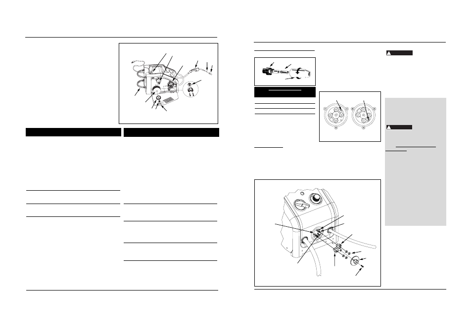
2. Remove cover screw and polarity
cover.
3. Remove four nuts from polarity
studs.
4. Pull out polarity bus bar and rotate
it 90°. Reinsert aligning groove with
the correct rib in polarity box.
Upper right rib marks the MIG
position; lower right rib marks the
Flux position. (See Figure 4c.)
5. Reinstall four nuts and tighten
securely.
6. Reinstall polarity cover and cover
screw.
7. Make sure arrow on polarity cover
points to desired setting.
Assembly
(Continued)
POLARITY
MIG welding wire requires electrode
positive electrical polarity. Flux welding
wire requires electrode negative
electrical polarity. The welder is factory
set for flux welding wire.
To Change Polarity (See Figure 4b)
NOTE: The arrow on the Polarity Cover
points to the current polarity setting.
TOOLS NEEDED: Phillips screwdriver
and 10mm socket wrench.
1. Unplug power cord from socket.
40 Sp
1 Ensamble del soplete y la manguera
(MIG, 2,44 m, WG2060)
WC403660AV 1
Ensamble del soplete y la manguera
(MIG, 3,05 m, WG2064)
WC404100AV 1
2 Punta de contacto - 0,035” (0,9 mm)
WT501400AV 1
Punta de contacto opcional – 0,024”
(0,6 mm) Paq. 4
WT501200AJ †
Punta de contacto opcional – 0,030”
(0,8 mm) Paq. 4
WT501300AJ †
Punta de contacto opcional – 0,035”
(0,9 mm) Paq. 4
WT501400AJ †
3 Boquilla
WT502100AV 1
4 Portabobinas
WC500805AV 1
5 Ensamble de la placa de conducción
WC500800AJ 1
6 Vástago y rejilla
WC707018AV 1
7 Retén de la bobina
WC707024AV 1
8 Resorte del retén de la bobina
WC707026AV 1
9 Anillo del retén de la bobina
WC707023AV 1
10 Alambre de soldar con fundente – 0,030”
(0,8 mm) Bobina de 2 lb. (0,9 kg) (E71T-GS)
WE200001AV †
Alambre de soldar con fundente – 0,030”
(0,8 mm) Bobina de 10 lb. (4,54 kg) (E71T-GS
WE201000AV †
Alambre de soldar con fundente – 0,035”
(0,9 mm) Bobina de 2 lb. (0,9 kg) (E71T-GS)
WE200501AV †
Alambre de soldar con fundente – 0,035”
(0,9 mm) Bobina de 10 lb. (4,54 kg) (E71T-GS)
WE201500AV †
Alambre de soldar MIG – 0,024”
(0,6 mm) Bobina de 2 lb (0,9 kg) (ER70S6)
WE300001AV †
Alambre de soldar MIG – 0,024”
(0,6 mm) Bobina de 11 lb. (5 kg) (ER70S6)
WE301500AV †
No de
No De
Ref.
Descripción
Componente Cant
Modelos WG2060 y WG2064
Alambre de soldar MIG – 0,030” (0,8 mm)
Bobina de 2 lb. (0,9 kg) (ER70S6)
WE300501AV †
Alambre de soldar MIG – 0,030” (0,8 mm)
Bobina de 11 lb. (5 kg) (ER70S6)
WE302000AV †
Alambre de soldar MIG – 0,035” (0,9 mm)
Bobina de 2 lb. (0,9 kg) (ER70S6)
WE301001AV †
Alambre de soldar MIG – 0,035” (0,9 mm)
Bobina de 11 lb. (5 kg) (ER70S6)
WE302500AV †
Alambre de soldar MIG – 0,030” (0,8 mm)
1 lb (0,45 kg) de aluminio (ER5356)
WE303001AV †
11 Retén del recipiente con 4 tornillos
WC302600AJ 1
12 Conexión dentada de la manguera
(externa)
WC403900AV 1
▲ Accesorio de conexión rápida
(interna)
WC403901AV 1
13
▲ Manguera de gas – 22” (56 cm)
WC403902AV 1
14
▲ Abrazadera de la manguera
WC403903AV 2
15
▲ Regulador (WG2060)
WC803500AV 1
▲ Regulador (WG2064)
WC803600AV 1
16
▲ Máscara de mano
(no se incluyen lentes)
WC801700AV 1
17
▲ Lentes oscuros
(para máscara de mano)
WC801100AV 1
18
▲ Martillo/cepillo cincelador
WC803400AV 1
19
▲ Etiqueta adhesiva de seguridad
DK688509AV 1
20
▲ Juego de la barra de polaridad
WC403128AV 1
21
▲
Pinza de tierra (WG2060)
WC100300AV 1
▲
Pinza de tierra (WG2064)
WC100600AV 1
22
▲
Guantes para soldar (sólo WG2064)
WT200501AV 1
▲ No se muestra
† Accesorio opcional
No de
No De
Ref.
Descripción
Componente Cant
Soldadora Por Arco Con Alimentación de Cable
3
4
1
8
9
2
11
10
7
12
6
5
Figura 14 - Piezas de Repuesto
Para Ordenar Repuestos o
Asistencia Técnica, Sírvase Llamar
al Distribuidor Más Cercano a Su
Domicilio
Dirija toda la correspondencia a:
Campbell Hausfeld
Attn: Customer Service
100 Mundy Memorial Drive
Mt. Juliet, TN 37122 U.S.A.
Sírvase suministrarnos la siguiente información:
- Número del modelo
- Número de Serie (de haberlo)
- Descripción y número del repuesto según la
lista de repuestos
Shielding Gas Preparation
Improper handling
and maintenance of
compressed gas cylinders and regulators
can result in serious injury or death!
Always secure gas cylinders to tank
bracket kit, a wall or other fixed support
to prevent cylinder from falling over.
Read, understand and follow all
compressed gas and equipment
warnings in the safety instructions.
NOTE: Shielding gas is not required if
flux-core welding wire is used.
GAS TYPES
There are 3 types of gas generally used
for gas metal arc welding; 100% argon,
a mixture of 75% argon and 25%
carbon dioxide (C25) or 100% carbon
dioxide.
Use ONLY the type
of gas recommended
for your welder. Use ONLY an inert, non-
flammable type of gas. Failure to do so
will result in a very hazardous situation.
NOTE: 100% carbon dioxide is not
recommended due to unsatisfactory
weld beads.
The 75/25 mixture is recommended for
general steel welding. For aluminum
welding, use 100% argon. Cylinders of
either type gas may be obtained at your
local welding supply outlet. Secure
cylinder in place on your welding
machine or other support to prevent the
cylinder from falling over.
Obtaining Correct Gas Type. The gas
used in any welding application for your
welder must be an INERT, NON-
FLAMMABLE TYPE. You can get the type
of gas needed from a nearby welding
gas distributor (often found in the
yellow pages under “Welders” or
‘Welding Equipment”).
REGULATOR
An adjustable regulator without gauges
is supplied with the WG2060. The
regulator supplied with the WG2064
includes two gauges. The regulator
provides a constant shielding gas pressure
and flow rate during the welding process.
Each regulator is designed to be used
with a specific gas or mixture of gases.
The argon and argon mixture use the
same thread type. The 100% carbon
dioxide uses a different thread type. An
adapter is available at your local welding
gas supplier to change between the two.
!
DANGER
!
DANGER
5
Models WG2060 and WG2064
www.chpower.com
Contact Tip Markings
Mark
Wire Size
0.6 mm
.024"
0.8 mm
.030”
0.9 mm
.035”
Torch Diffuser
Contact Tip
Nozzle
Figure 4 - Torch Nozzle
Figure 4b
Polarity box
Flux rib
Polarity bus bar
Nuts
Cover screw
Polarity
cover
Groove
Polarity studs
MIG rib
Figure 4c
MIG position
Flux position
Upper right—
MIG rib
Lower right—
Flux rib