Mac 10, Ledc, 4x4 fan filter unit – Envirco MAC 10 LE-DC User Manual
Page 5: Installation
MAC 10
®
LEDC
4x4 Fan Filter Unit
5
Innovators in Clean Air Technology | www.envirco.com | Operation & Maintenance
I n s t a l l a t i o n & S e r v i c e M a n u a l
■
Installation
Note: The MAC 10 LEDC Fan Filter Unit is completely assembled at the factory with the exception of the optional ¼” (0.64
cm)-20 eyebolts that are used when hanging the unit from an engineered design support system and installation of the HEPA/
ULPA filters (eyebolts not included and need to be ordered separately, p/n 222449-001).
Step 1. Carefully remove the unit from the shipping carton and inspect for any damage that may have occurred during
transportation (See Figure 1). Using the two handles attached to the lid, two workers minimum, are required to lift the unit from
the box.
Recommendation:
Review mode settings
at this time as specified
for installation
(see page 7 for controls).
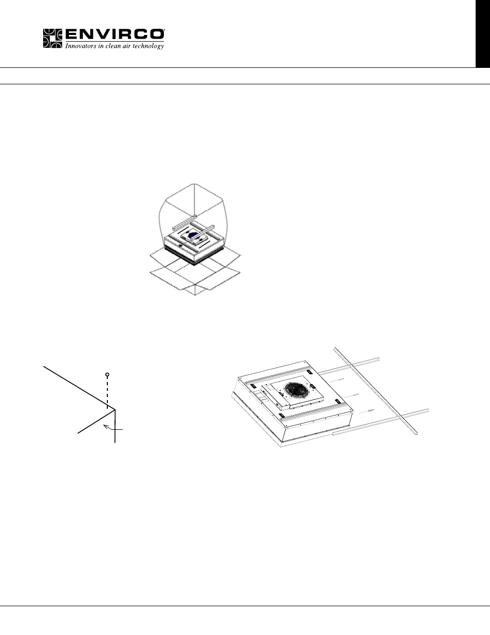
Figure 1: Unboxing
Step 2. If using rigidly supported grid (usually 2” (50 mm) or wider), raise unit through ceiling and lower onto the gasketed grid.
If using a flexible grid (typically supported with wires), the unit must be secured to an engineered design support system with
s-hooks and chain. Screw the four eyebolts into the nutserts on the lid assembly before lifting into an overhead position (see
Figure 2).
Note: Confirm fan dimensions to match T-grid dimensions.
Figure 2: Hanger Supports Figure 3: Front Load Option
Step 2.1. It is recommended that you front load your MAC 10 4x4 to your T-Grid system by running your main T-Grid and two
cross Ts (install fan box into grid), then running your main T again (see Figure 3).
Step 2.2. If using a support grid, continue...
Step 3. Raise the unit and secure it into place using the chosen support system method suspended from a structural support
bracing.
Step 4. Have an electrician wire the unit to the appropriate voltage, according to the wiring diagram (page 17), and all national
and local electrical codes. All units are equipped with a three position terminal block for field connection. Verify correct single-
phase power, before energizing units.
Step 5. Turn on the power using the two position rocker switch (ON/OFF) located on the electrical box. For RSR/E units, let
the unit run for a few hours to purge off particulate that may be adhered to the inside of the unit before installing the filters. Do
not run fan at full speed as this may cause overload condition.
Note: Your fan filter has been shipped separately.
EYEBOLT
FAN FILTER
UNIT
Note: When ordering RSR and RSRE
units, the HEPA filters will be shipped
separately to be installed into units
after the fan box has been installed.