Majestic fireplaces, Uvc / uvs vent-free heaters, Safety devices – CFM UVC43 User Manual
Page 5: Description, Clearance to combustibles
5
Majestic Fireplaces
®
UVC / UVS Vent-Free Heaters
20000135
Safety Devices
Adequate combustion and ventilation air must be pro-
vided. The flow of combustion and ventilation air MUST
NOT be obstructed.
Provide adequate clearances around the air opening
into the combustion chamber; and adequate accessibili-
ty clearance for servicing and proper operation. NEVER
obstruct the front opening of the heater or cover the top
and bottom louvres (grilles).
These heaters are equipped with a pilot system fea-
turing an Oxygen Depletion Sensor (O.D.S.) shut-off
device. All unvented heaters are required to have this
system. The O.D.S. pilot will shut down the heater
when there is not enough fresh air available.
Report any parts damaged in shipment to your dealer.
Description
The UVC vent-free heaters are unique in featuring two
catalytic filters and a frame window with glass that actually
clean room air as well as give excellent zone heating.
The UVS vent-free heaters use a frame window with
screen mesh that does not use any catalytic filters.
Each model is available as Natural or Propane gas,
equipped with a standing pilot.
Design-certified to ANSI Z21.11.2a-2003. Gas-Fired
Room Heaters — Vol. II, Unvented Room Heaters.
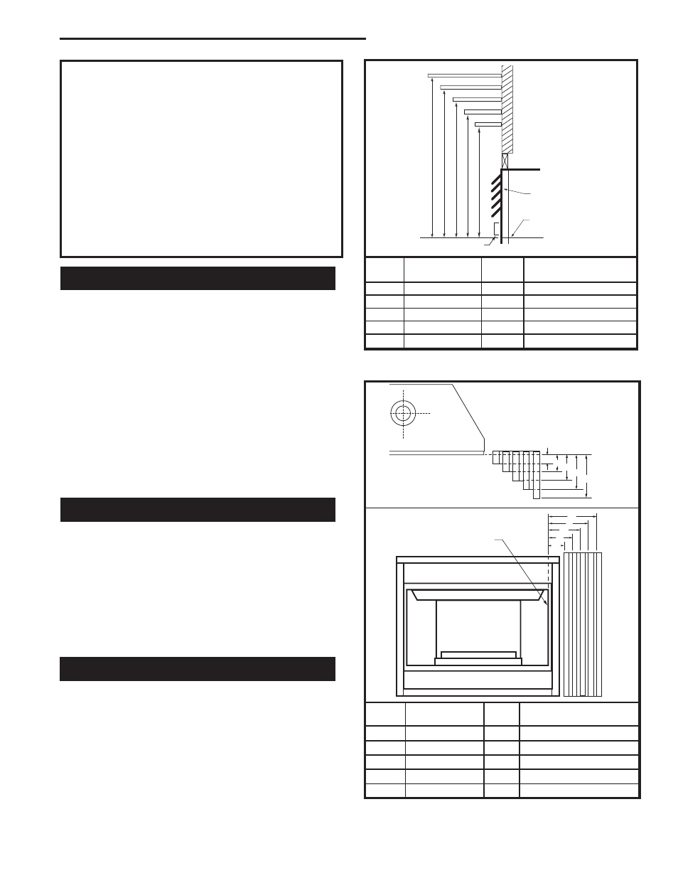
Clearance to Combustibles
Top of unit to ceiling
36" (914 mm)
Front of unit to combustibles
36 (914 mm)
Appliance
Top .............................................................. 0" (0 mm)
Bottom ......................................................... 0" (0 mm)
Sides ........................................................... 0" (0 mm)
Back ........................................................... 0" (0 mm)
Perpendicular sidewall ............................ 6" (152 mm)
A B C D E
V
W
X
Y
Z
Fireplace
CFM146
DV Mantel Chart
7/5/01 sta
Ref.
Mantel
Ref.
Mantel From Top
Shelf Depth
of Comb. Chamber
V
10" (254 mm)
A
19" (483mm)
W
8" (203 mm)
B
17" (432mm)
X
6" (152 mm)
C
15" (381mm)
Y
4" (101 mm)
D
13" (330mm)
Z
2" ( 51 mm)
E
11" (279mm)
Fig. 3a Combustible mantel minimum installation.
CFM146
Top of
Combustion Cham-
ber
Top Louvre
Assembly
Bottom of Door Trim
Mantel
Mantel Leg From Side
Ref.
Leg Depth
Ref.
of Comb. Opening
F
10" (254 mm)
K
11¹⁄₂" (292 mm)
G
8" (203 mm)
L
9¹⁄₂" (241 mm)
H
6" (152 mm)
M
7¹⁄₂" (191 mm)
I
4" (101 mm)
N
5¹⁄₂" (101 mm)
J
2" ( 51 mm)
O
3¹⁄₂" (89 mm)
J
F
G
H
I
Mantel
Leg
CFM164a
Mantel Leg Chart
06/22/01 sta
CFM170
DV Builder Front
View
O
N
M
L
K
Side of
Combustion Chamber
CFM164a
CFM170
Fig. 3b Combustible mantel leg minimum installation.
IMPORTANT:
Please Review the Following Carefully
It is normal for fireplaces fabricated of steel to give off some
expansion and/or contraction noises during the start up or cool
down cycle. Similar noises are found with your furnace heat
exchanger or car engine.
It is not unusual for your gas fireplace to give off some odor the
first time it is burned. This is due to the curing of the paint and
any undetected oil from the manufacturing process.
Please ensure that your room is well ventilated - open all
windows.
It is recommended that you burn your Vermont Castings Majestic
Products fireplace for a least six (6) hours the first time you use
it. If optional fan kit has been installed, place fan in the "OFF"
position during this time.