Installing the dle-55ra on your airplane – DLE 55RA User Manual
Page 7
7
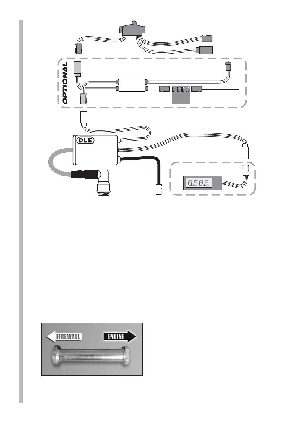
Ignition Wire
(To Spark Plug)
Ignition Control Switch Wire
(To On/Off Switch)
Pick-Up
Sensor Wire
(To Sensor
On Engine)
Tachometer Lead/
RPM Signal Output
ELECTRONIC IGNITION
SYSTEM
Battery Lead
Charge Lead
Switch
(Not included)
Tachometer
(Not included)
DLEG5525
OPTO Gas Engine Kill Switch
(DLEG9205, not included)
OPTIONAL
Ignition
Battery Lead
Ignition
Rx Batt
Lead
Rx
LED
KILL
SWITCH
Installing the DLE-55RA on Your Airplane
Note: The DLE-55RA must be installed on at least a 9.5mm [3/8"]
thick 5-ply plywood fi rewall. The fi rewall must be securely glued to
the airplane. Use triangle stock and pin the fi rewall with hardwood
dowels to reinforce the fi rewall glue joints. Never install the
DLE-55RA onto a fi rewall thinner than specifi ed because it may fail
due to the power of the engine.
Note: The length of the engine from the back of the engine mount
stand offs to the propeller drive washer is 6.73" [171mm].
1. Use the supplied template (on the back cover of this manual) to
drill the engine mounting bolt holes.
2. Install the standoffs to the
fi rewall using (4) 5x20mm SHCS
with 5mm lock washers and 5mm
washers (not included) from
the back side and through the
fi rewall into the standoffs. Use
some threadlocking compound,
such as Great Planes
®
Pro
™
Threadlocker (GPMR6060), on the
screws. Next install the DLE-55RA to the standoffs using the
included (4) 5x20mm SHCS with 5mm washers. Be sure to also
use threadlocker when mounting the engine to the standoffs.