Appendix a. bridge mode operation, Not in use, No ti nu s e – D.A.S. Audio Energy Series User Manual
Page 23: 12 x factor 8t, Watts, 26 x factor 8t, A jumper must be connected between 0v terminals, Manual del usuario user’s manual / energy
7
APPENDIX A. Bridge mode operation
Entrada de señal / Signal Input
CH A
12 x
factor 8T
1
22
3
4
5
7.5
30
15
15
60
30
30
60
3.7
15
7.5
1.9
7.5
3.7
1
3.7
1.9
50 V
70 V
100 V
WATTS
D
O
N
O
T
D
O
N
O
T
U
S
E
U
S
E
9
10
12
140V 200V
CHANNEL A
70V
100V
100V
25V
25V
70V
100
100
70
0
70
0
SPEAKER
OUTPUT
CHANNEL B
BRIDGE
SPEAKER OUTPUT
WARNING: TO REDUCE RISK OF FIRE OR ELECTRIC SHOCK
DO NOT EXPOSE THIS EQUIPMENT TO RAIN OR MOISTURE
VER MANUAL DE INSTRUCCIONES PARA LA CONEXIÓN
REFER TO INSTRUCTIONS MANUAL FOR CONNECTION
ANSCHLUSSWEISE BITTE DER ANLEITUNG ENTNEHMEN
VOIR MANUEL D'INSTRUCTIONS POUR LA CONNEXION
EUROPEAN
PRODUCT
CHANNEL B
CHANNEL A
ON
OFF
STEREO
P
A
R
A
LLEL
BRIDGED
not
in
use
Serial Number:
D.A.S. AUDIO S.A. (Valencia) SPAIN
MODEL:
220V-240V
4A 50Hz-60Hz
OUTPUT PWR PER CH/IMP: 450W/70V 100V
E-8T
N1918
140V
200V
CHANNEL A
70V
100V
100V
25V
25V
70V
CHANNEL B
not
in
use
CAUTION
ATTENTION
RISK OF ELECTRIC SHOCK
DO NOT OPEN
DANGER D’ELECTROCUTION
NE PAS OUVRIR
SIGNAL
INPUT
BRIDGE
MADE IN SPAIN
100
100
70
0
70
0
1 2 3 4 5 6 7 8 91
1
0
2
1
1
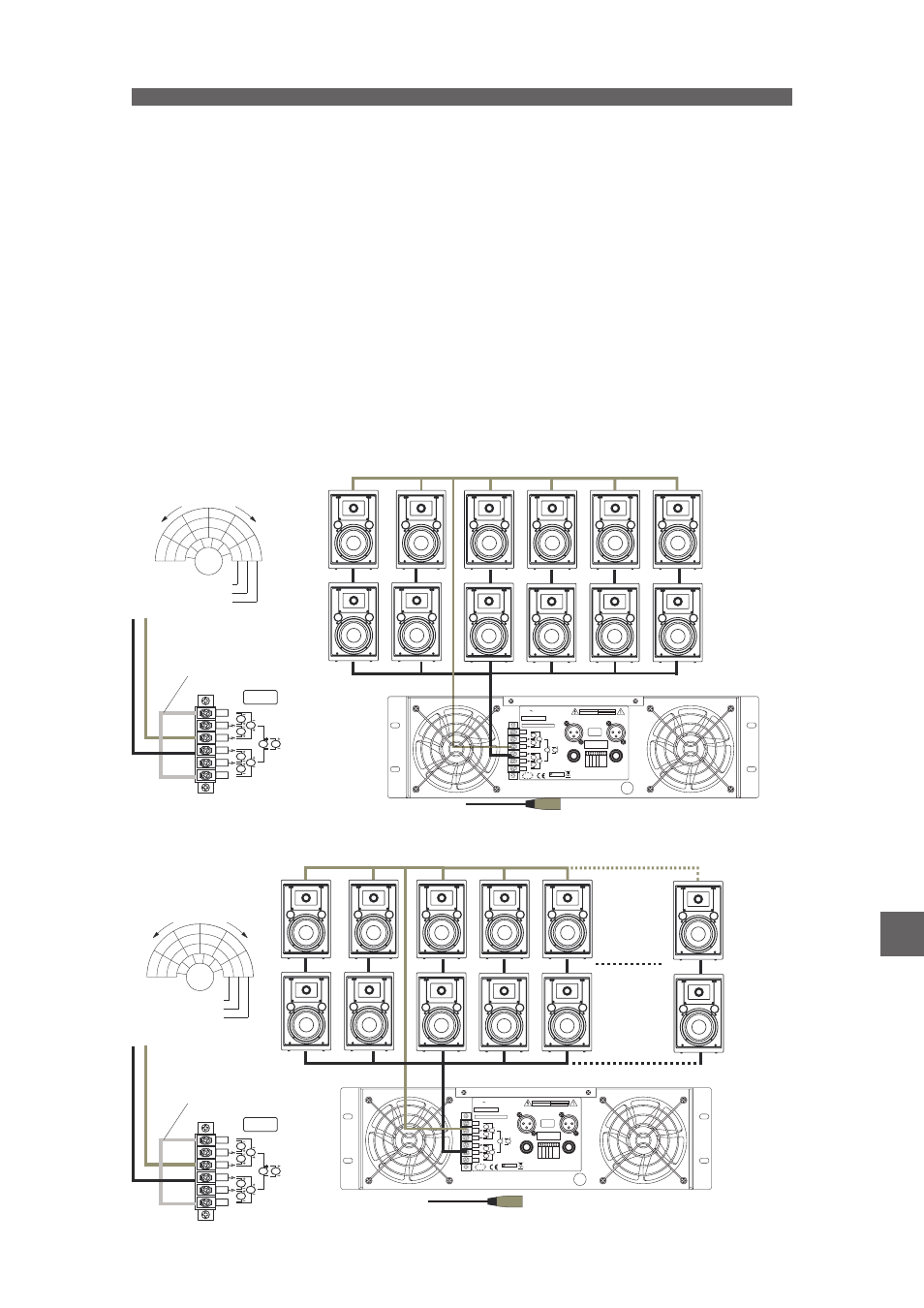
To operate in bridge mode, follow these steps:
1. Swich off the amplifier.
2. Turn volume control potenciometers on the front panel to minimum position (fully counter-clockwise).
3. Connect input signal to channel A.
4. Set mode multi-switch to “
”.
5. Connect speakers as follows: If the selected output voltage is 100V, the two speaker cables must be connected to the
100V terminal outputs.
6. A jumper must be connected between 0V terminals.
7.
.
8.-
.
NOTE 1: Always use Class II cables.
NOTE 2: Do not connect low impedance loads to a 70V / 100V line amplifier.
The following are several examples of bridge mode operation with distributed lines:
The first one is an example for an
amplifier, which delivers 790 W in bridge mode at 100 V.
The load is 12 x
, and the power selectors are at 100 V / 60 W (total:720W).
BRIDGE
Turn volume control potentiometers on the front panel to maximum position (fully clockwise)
Control volume levels from the mixer or pre-amp only
E-8T
factor8T
In the second example an
amplifier is used, which delivers 790 W in bridge mode at 70 V. The load is
26 x
, and the power selectors are at 70 V / 30 W (total:780W).
E-8T
factor 8T
A jumper must be connected
between 0V terminals.
SPEAKER OUTPUT
WARNING: TO REDUCE RISK OF FIRE OR ELECTRIC SHOCK
DO NOT EXPOSE THIS EQUIPMENT TO RAIN OR MOISTURE
VER MANUAL DE INSTRUCCIONES PARA LA CONEXIÓN
REFER TO INSTRUCTIONS MANUAL FOR CONNECTION
ANSCHLUSSWEISE BITTE DER ANLEITUNG ENTNEHMEN
VOIR MANUEL D'INSTRUCTIONS POUR LA CONNEXION
EUROPEAN
PRODUCT
CHANNEL B
CHANNEL A
ON
OFF
STEREO
P
A
R
ALLEL
BRIDGED
n
o
ti
nu
s
e
Serial Number:
D.A.S. AUDIO S.A. (Valencia) SPAIN
MODEL:
220V-240V
4A 50Hz-60Hz
OUTPUT PWR PER CH/IMP: 450W/70V 100V
E-8T
N1918
140V
200V
CHANNEL A
70V
100V
100V
25V
25V
70V
CHANNEL B
n
o
ti
nu
s
e
CAUTION
ATTENTION
RISK OF ELECTRIC SHOCK
DO NOT OPEN
DANGER D’ELECTROCUTION
NE PAS OUVRIR
SIGNAL
INPUT
BRIDGE
MADE IN SPAIN
100
100
70
0
70
0
1 2 3 4 5 6 7 8 91
1
0
2
1
1
2
4
6
26
Entrada de señal / Signal Input
CH A
26 x
factor 8T
7.5
30
15
15
60
30
30
60
3.7
15
7.5
1.9
7.5
3.7
1
3.7
1.9
50 V
70 V
100 V
WATTS
D
O
N
O
T
D
O
N
O
T
U
S
E
U
S
E
1
3
5
25
140V 200V
CHANNEL A
70V
100V
100V
25V
25V
70V
100
100
70
0
70
0
SPEAKER
OUTPUT
CHANNEL B
BRIDGE
A jumper must be connected
between 0V terminals.
EN
Manual del Usuario
User’s Manual
/ energy /