Comtrol RM II V.90 User Manual
Hardware installation card, Rocketmodemii™ v.90
Product Overview
The RocketModemII multimodem card is Hayes
®
compatible and contains four or six RJ11 modem ports,
depending on the model, that can operate at speeds up
to 56 Kbps.
RocketModemII features for this model include:
•
Four or six RJ11 modem ports
•
Bootable diagnostic tests on diskette
•
Individual software controlled modem reset
capability
•
Speaker
Note: See the Software Installation and Configuration
Guide for information about installing software,
the AT command set, and using the reset feature.
Note: If the Comtrol RocketModemII is not among the
modem models listed in your software
applications modem list, you can select
SupraFAXModem 288(336) for fax emulation and
Zoom Telephonics Zoom V.34X for modem
emulation.
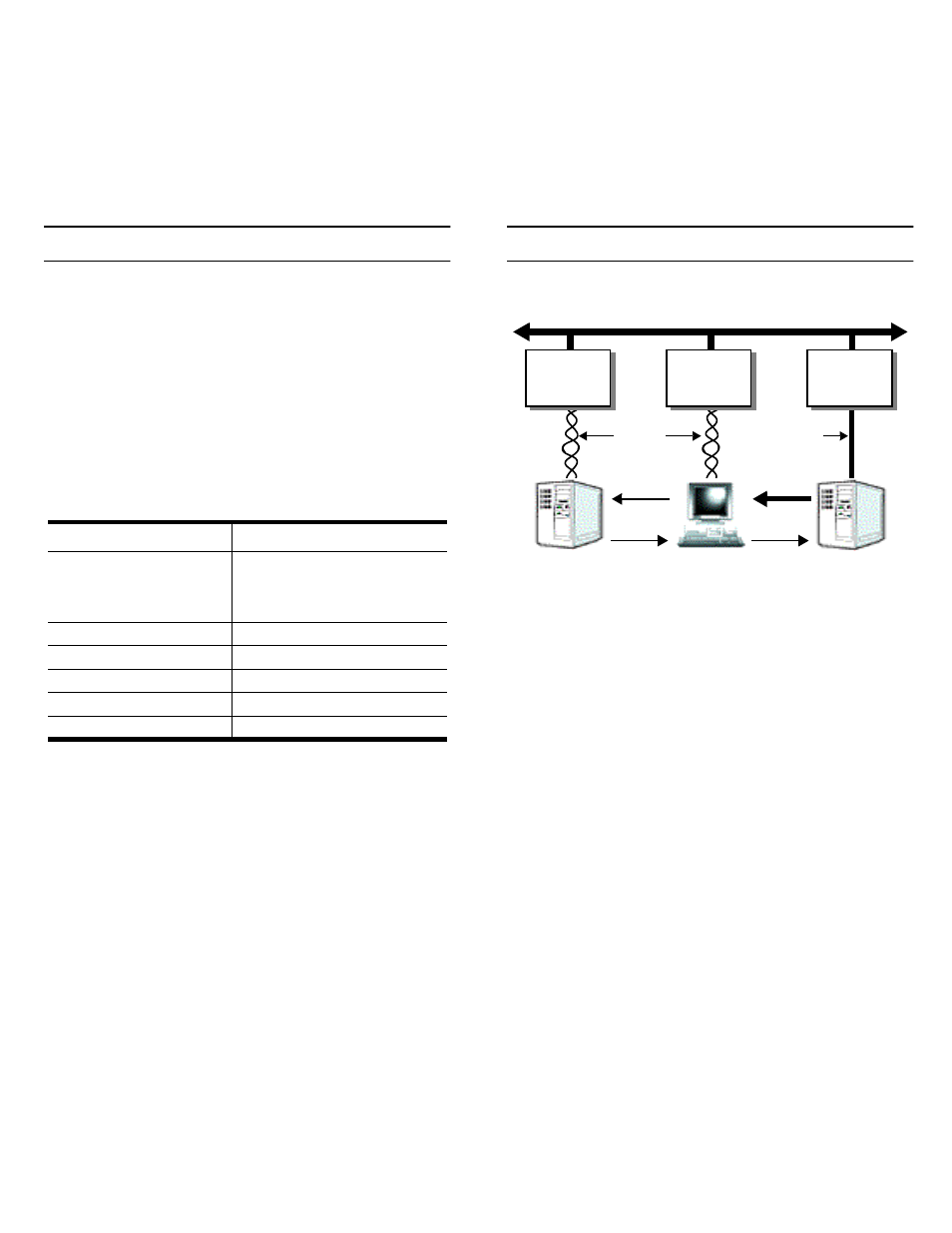
Utilizing V.90 Technology
All V.90 modems are analog line devices. The following
figure shows when you can and cannot achieve 56 Kbps.
•
V.90 modems can receive data at rates up to 56 Kbps,
provided the data is being transmitted by a digital
modem on a digital (e.g., T1 or ISDN) line.
•
V.90 modems can send data over analog (twisted
pair) phone lines at a maximum rate of 33.6 Kbps—
even if communicating with other V.90 modems.
•
The actual data rate achieved depends on the age
and condition of the analog phone lines, and may be
lower than 33.6 Kbps.
Characteristic
RocketModemII Support
Supported standards
V.90, K56Plus, V.34,
V.32turbo, V.32bis, V.32,
V.22bis, V.23, V.21, Bell
212A, Bell 183
Error correction
V.42, MNP2-4, MNP10
Data compression
V.42bis, MNP5
Fax group
Group 3
Fax class
Class 1.0 and Class 2
Reset
Software controlled
Digital
Server
V.90
Server
V.90
User
Telco
Office
Telco
Office
Analog
Telco
Office
Digital Telephone Network
Lines
Digital
Line
56K
33.6K
33.6K
33.6K
Data
Data
Rate
Rate
RocketModemII™ V.90
Hardware Installation Card
Document Outline
- Product Overview
- Utilizing V.90 Technology
- Installing the RocketModemII
- 1. Turn your computer off and remove the system unit cover.
- 2. Select an available PCI slot and remove the slot cover.
- 3. Write down the serial number of the RocketModemII.
- 4. Insert the RocketModemII in the expansion slot. Make sure it is seated securely.
- 5. Reinstall the expansion slot cover screw.
- 6. Connect standard RJ11 (telephone) cables between the RocketModemII ports and the phone line ja...
- 7. Power up the computer and run the Diagnostics program to verify that the RocketModemII is inst...
- 8. After the RocketModemII has successfully passed diagnostics, install and configure the device ...
- Port Identification
- Using the Diagnostics
- 1. Insert the Diagnostics diskette in the floppy drive.
- 2. Power up the machine. The diagnostic program starts automatically on boot-up.
- 3. Press any key to continue.
- 4. Press any key to continue.
- 5. Select the letter that corresponds to the model you installed, select NOT INSTALLED if you hav...
- a. Select the letter for the I/O address you used when installing the card. A list of valid IRQ i...
- b. Select the letter for the IRQ you used when installing the card.
- c. The diagnostic program loops back to Step 5.
- d. If you have more than one ISA RocketModem installed, repeat this step until you have entered t...
- 6. If the list is correct, press Y. If the information is not correct, press N to restart the dia...
- 7. After initialization completes, an option box displays at the bottom of the screen:
- 8. Press D to test the serial I/O and IRQ. (The T and M options are discussed under Terminal Mode...
- 9. Press any key to continue. If you have more than one card installed, the diagnostic repeats un...
- 10. Press any key to continue. The diagnostic displays a summary of the test results.
- 11. Press any key to continue.
- 12. Press Y to restart the diagnostic at Step 3 (for example, to enter Terminal Mode), or N to quit.
- 1. If there is more than one RocketModem installed, you are asked to select a card. Do so.
- 2. A numbered menu listing the ports on the selected card displays. You may also press H for help...
- 3. Enter a port number to select a modem. The Terminal Mode screen displays.
- 4. Type AT commands to communicate with the modem.
- 5. When you are done, press Esc to return to Step 2.
- 1. Select Port 1.
- 2. Enter AT&F0 to initialize the modem to factory default parameters.
- 3. Enter ATS0=1 to direct the modem to answer the phone on the first ring.
- 4. Press Esc to return to the port menu.
- 5. Select Port 2.
- 6. Enter AT&F0 to initialize the second modem.
- 7. Enter ATDxxx xxxx (where xxx xxxx is the phone number of the line connected to the first modem).
- 8. Press Esc.
- 9. Select Port 1. You should see RING and CONNECT messages.
- 10. Any keys you press while looking at Port 1 display when you look at Port 2. Likewise, any key...
- 11. To exit, on either of the ports enter the escape sequence +++. This enables you to enter ATH ...
- 12. To exit terminal mode and return to the port menu, press Esc.
- Using the Speaker
- Modem Cables
- FCC Notices
- 1. This equipment complies with Part 68 of FCC rules. On the bottom panel of the unit is a label ...
- 2. The RocketModemII uses FCC compliant modular plugs, it is designed to be connected to the tele...
- 3. If this equipment causes harm to the telephone network, the telephone company will notify you ...
- 4. The telephone company may make changes in its facilities, equipment, operations, or procedures...
- 5. If the equipment is causing harm to the network, the telephone company may request you to remo...
- 6. No repairs are to be made by you. Repairs are to be made only by Comtrol or its licensees. Una...
- 7. This equipment may not be used for public coin phone service provided by the Telephone Company...
- 8. The Telephone Consumer Protection Act of 1991 makes it unlawful for any person to use a comput...
- Operating Conditions
- Hardware Specifications
- Electromagnetic Compliance
- Technical Support
- RocketModemII™ V.90
- Hardware Installation Card