Comtrol RocketPort USB Modem Hub User Manual
Rocketport® usb modem hub hardware documentation
Product Overview
1 of 4
Product Overview
The RocketPort USB Modem Hub (RPUSBMH)
connects to a Universal Serial Bus (USB) port on a
PC. It is Hayes
®
compatible and contains four RJ11
modem ports that can operate at speeds up to 56
Kbps.
RocketPort USB Modem Hub series supports the
following features:
•
Four V.90/56K flex modem ports
•
Two downstream USB ports
•
“Plug-and-Play” and “Hot Plug” capability
•
Analog fax to 14.4 Kbps
•
Compatible with USB specification 1.0/1.1
•
Individual hardware modem reset capability
•
Windows 98 compatible
•
Speaker
Note: See the AT Command Set and the Software
Installation document for more information.
Note: If your software applications list does not
contain the Comtrol RocketPort USB Modem
Hub, you can select SupraFAXModem
288(336) for fax emulation and Zoom
Telephonics Zoom V.34X for modem
emulation.
The RocketPort USB Modem Hub uses an internally
generated 48 MHz controller specifically designed for
a USB port to operate four modem ports. This device
and its software enable the USB interface to be
transparent to the peripheral and requires no
firmware changes. This makes it possible for
modems to easily interface with a USB port.
Installing the Hardware
Using a Third-Party Power Supply
Comtrol supplies a power adapter with the unit.
If you want to connect a
third-party power supply to
the RocketPort USB Modem
Hub, it must be a UL Listed
Direct Plug-In Power Unit
identified as Class 2 and
rated 5V DC +/- 10% and 2A
+/- 20%. See the previous polarity figure and
compare it to the one marked on the back of the unit
above the connector.
Note: Failure to use the correct power supply may
damage the unit and void the warranty.
LED Description
•
The Power light (amber) on the front of the unit
indicates that there is power coming into the unit.
Note: This does not signify that the unit is working
properly. Use WCOM32 supplied with the
driver to diagnose possible problems with the
unit.
•
One LED for each modem (4). Each LED indicates
that the modem has been connected.
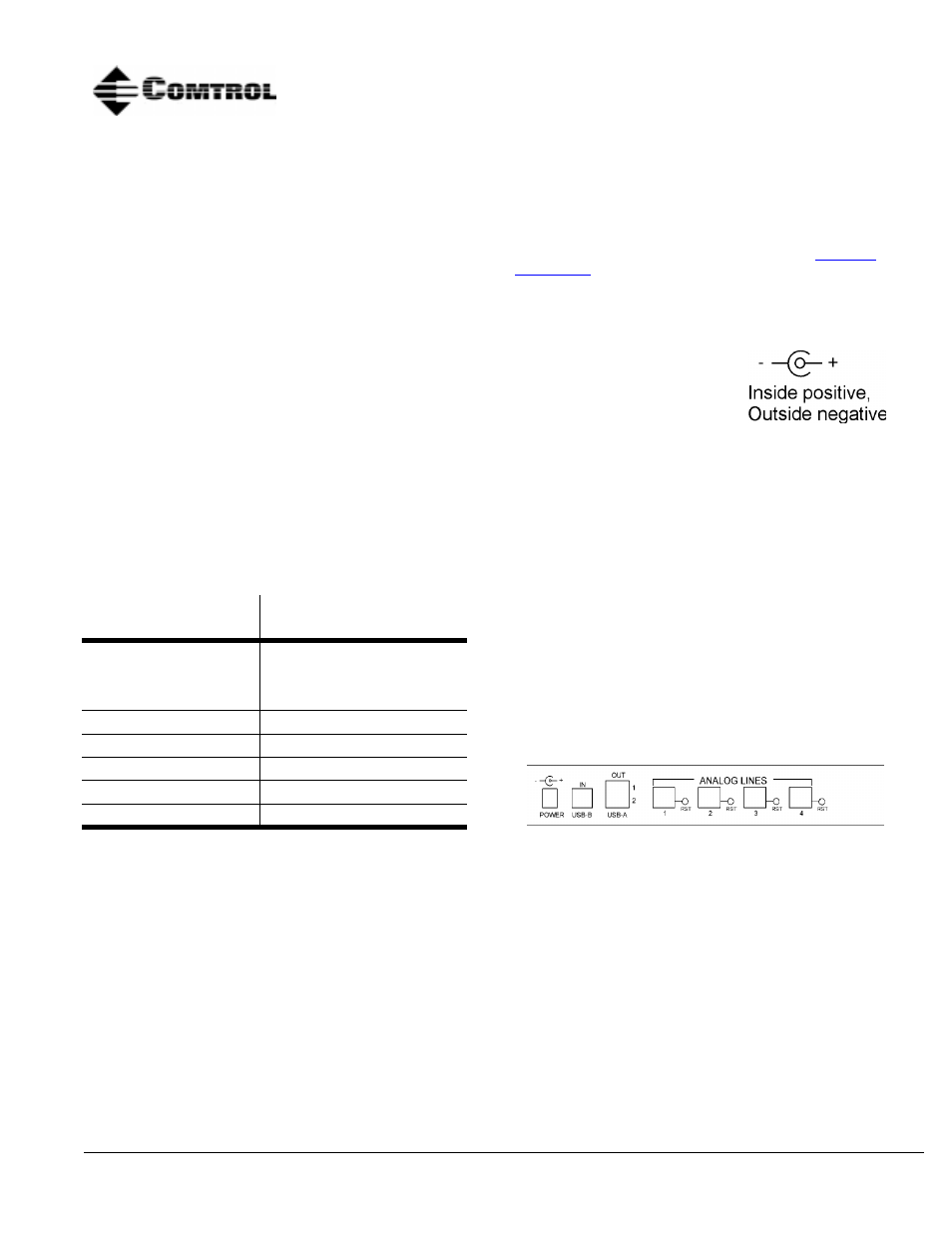
Port Identification
The back plate includes the following connections
and switches:
•
Power: 5V DC power supply
•
USB-B: USB type B Upstream Port
•
USB-A: Two USB type A Downstream Ports
•
Analog Lines: Four RJ11 modem ports with
manual reset.
•
Manual Reset Switch
Reset a modem if it locks up during use. Use a
sharp thin object (like a paper clip) to push the
recessed reset switch.
Characteristic
RocketPort USB Modem
Support
Supported standards
V.90, K56flex, V.34, V.32
bis, V.32, V.23, V.22 bis,
V.22 V.21, Bell 212A, Bell
103
Error correction
V.42 LAPM, MNP 2-4
Data compression
V.42 bis, MNP 5
Fax group
Group 3
Fax class
Class 1 and Class 2
Reset
Hardware controlled
RocketPort® USB Modem Hub
Hardware Documentation