Rj45 – Comtrol 485 RocketPort User Manual
Page 5
RocketPort® 485 Hardware Installation
5 of 8
*
Ports 1 and 2 can be either RS-232 or RS-485, while
Ports 3 through 8 are RS-232 only. All RS-232 control
signals are present in RS-485 mode, but not used.
** Ports 3 - 8 can be configured to carry +5V on Pin 9.
Do not use the +5V Power feature with the
Quad/Octacable Using Power feature with
interfaces other than the DB9 box may result in
unacceptable voltage loss.
Building DB9 Female Loopback Plugs or Cables
To perform loopback testing of DB9
ports in RS-232 mode, obtain or
create a female DB9 connector with
the following pins wired together:
•
Pins 2 to 3
•
Pins 7 to 8 to 9
•
Pins 1 to 4 to 6
Note: If you use the +5V Power feature, either remove the
jumper or disconnect the power supply cable before
running the diagnostics. If you do not do so, the
diagnostics fail.
To test DB9 ports in RS-485 mode, obtain two female DB9
connectors and create a cable with the following wiring:
RJ45 Interfaces
The Octacable RJ45 fanouts use RJ45 connectors.
RJ45 Pinouts
The RocketPort 485 uses RJ45 connectors with the pins
numbered as shown below:
Depending on jumper configuration, the pins carry the
following values:
*
Ports 1 and 2 can be either RS-232 or RS-485, while
Ports 3 through 8 are RS-232 only. All RS-232 modem
control signals are present in RS-485 mode, but not
used.
While the RocketPort 485 card can be configured
to supply +5V, this voltage is not accessible on
the RJ45 connector. Therefore this option should
not be used with the Octacable RJ45.
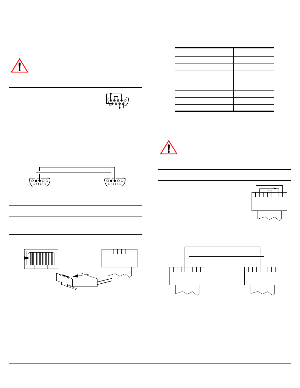
Building RJ45 Loopback Plugs or Cables
To perform loopback testing of RJ45
ports in RS-232 mode, obtain or
create an RJ45 connector with the
following pins wired together:
•
Pins 4 to 5
•
Pins 1 to 8
•
Pins 2 to 6 to 7
To test RJ45 ports in RS-485 mode,
obtain two RJ45 connectors and
create the cable shown below:
Caution
Pin 1
Pin 5
Pin 6
Pin 9
RS-232 (Back View)
Pin 1
Pin 5
Pin 6
Pin 9
Pin 1
Pin 5
Pin 6
Pin 9
Pin 2 (TRX-)
Pin 3 (TRX+)
RS-485 (Back View)
Pin 1
Receptacle
1
8
RJ45 Plug
Top View
Cable
Pin 1
Pin
RS-232 Signal
RS-485 Signal
1
RTS
Not used*
2
DTR
Not used*
3
Signal ground
Signal ground
4
TxD
TRX+
5
RxD
TRX-
6
DCD
Not used*
7
DSR
Not used*
8
CTS
Not used*
Caution
1
8
Plug
Top View
Cable
RS-232
1
8
Plug
Top View
Cable
1
8
Plug
Top View
Cable
Pin 5 (TRX-)
Pin 4 (TRX+)
RS-485