Introduction, Installation overview – Comtrol ES8508 Series Quick Start User Manual
Page 2
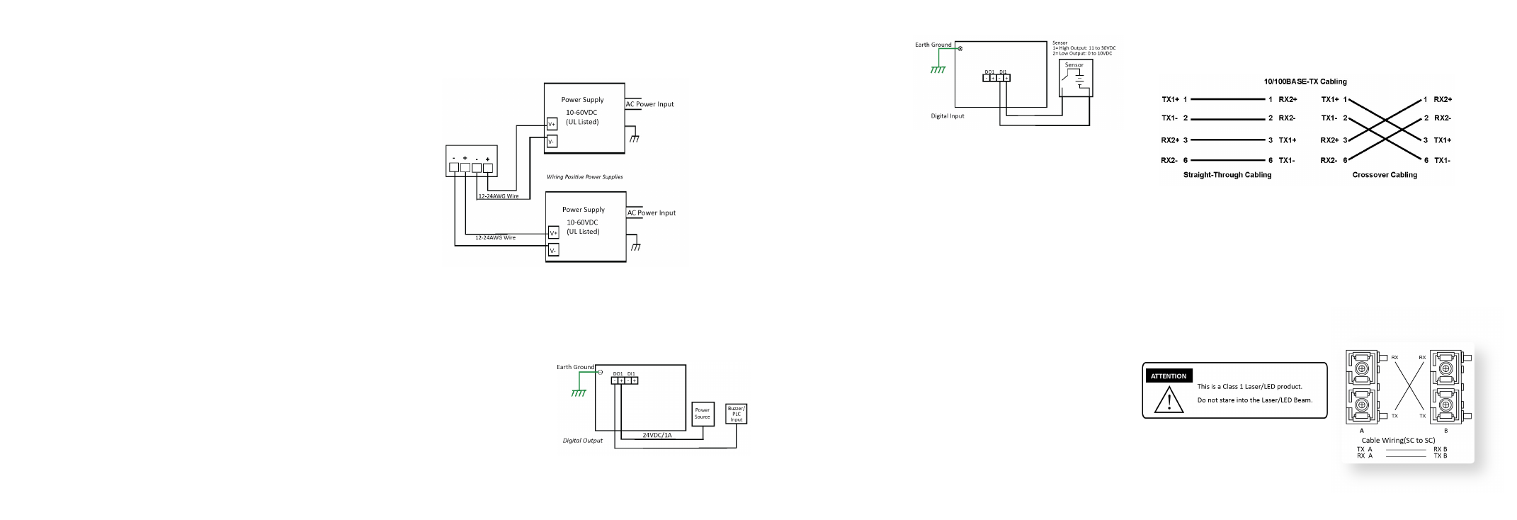
Wiring the Digital Input
The digital input (DI) contacts
are on the terminal block
connector on the bottom of the
ES8508. The contacts accept
one external DC type signal input
and can be configured to send
alert message through Ethernet
when the signal is changed.
The DI supports isolated input circuit with digital high level input of 11VDC
to 30VDC and digital low level input 0VDC to 10VDC. Do not apply a higher
voltage than the specification; it may cause internal circuit damage or a
cause an incorrect DI action.
Grounding the ES8508
Wire the earth ground to ensure the system is not damaged by noise or
any electrical shock, we recommend that you to make a direct connection
between the ES8508 and earth ground.
Using a screw driver, loosen the earth ground screw on the bottom of
the ES8508 and then tighten the screw after the earth ground wire is
connected.
Mounting the ES8508
The DIN rail clip is attached to the ES8508.
1. Insert the upper end of DIN rail clip into the back of DIN rail track from
its upper side.
2. Lightly push the bottom of DIN rail clip into the track.
3. Verify that the DIN rail clip is tightly attached on the track.
Connecting RJ45 Ports
Connect one end of an Ethernet cable into the Ethernet port of the ES8508
and the other end to the attached networking device. The RJ45 ports
support 10/100Mbps half/full-duplex. All RJ45 ports auto-detect the signal
Power should be disconnected from the power supply before connecting
it to the switch. Otherwise, your screwdriver blade can inadvertently short
your terminal connections to the grounded enclosure.
Wiring the Alarm Relay Output
The alarm relay output or digital output (DO) contacts are on the terminal
block connector on the bottom of the ES8508.
The relay contact supports up to 1A at 24VDC. Do not apply voltage and
current higher than the specifications.
The alarm relay output is
controlled by the pre-defined
operating rules. To activate the
alarm relay output function, refer
to the
RocketLinx ES8508
Series User Guide.
INTRODUCTION
The RocketLinx ES8508 series features advanced Layer 2 management
and security for deployment in mission critical networking applications.
The RocketLinx ES8508 series includes the following models:
•
ES8508 with 8 Fast Ethernet ports
•
ES8508F with 6 Fast Ethernet ports and 2 fiber ports (100BASE-FX
Single-Mode and Multi-Mode models)
•
ES8508-XT with 8 Fast Ethernet ports with an extended temperature
range
•
ES8508F-XT with 6 Fast Ethernet ports and 2 fiber ports
(100BASE-FX Single-Mode and Multi-Mode models) with an extended
temperature range
The different ES8508 models are simply referred to as the ES8508 unless
there is model specific information.
See the Comtrol website for complete product specifications.
INSTALLATION OVERVIEW
You can use the following overview to install the ES8508. If you need
more detailed installation and configuration information, you can refer
to the
RocketLinx ES8508 Series User Guide, which is available on the
RocketLinx CD or you can download the latest version.
Wiring the Power Inputs
The ES8508 provides redundant power, reverse polarity protection, and
accepts a positive or negative power source but PW1 and PW2 must apply
to the same mode. The recommended working voltage is 24VDC with an
input range of 10-60VDC and a maximum power consumption of 15W.
1. Insert the positive and negative wires into PW+ and PW- contacts
(PW1 and PW2). You can connect a single power supply or two power
supplies depending on your requirements.
2. If both power inputs are connected, the ES8508 will be powered from
the highest connected voltage. The unit can be configured to signal an
alarm for loss of power in either PW1 or PW2.
3. Tighten the wire-clamp screws to prevent the wires from being
loosened.
1
2
3
4
from connected devices to negotiate the link speed and duplex mode. Auto
MDI/MDIX allows users to connect another switch, hub, or workstation
without changing straight through or crossover cable.
Link/Act LEDs are lit to indicate traffic and link status, see the LEDs
subsection for more information.
Always make sure that the cables between the switches and attached
devices (for example, switch, hub, or workstation) are less than 100 meters
(328 feet). You should use 10/100BASE-TX: Category 5 Cable or higher.
Connecting Fiber Ports (ES8508F/ES8508F-XT Models Only)
Connect the fiber port to another Fiber Ethernet device using the following
diagram. An improper connection will cause the fiber port to not work
properly. The fiber port is a standard or square connector (SC). Make sure
that the fiber mode of the cable matches the fiber mode of the ES8508
(Single-Mode or Multi-Mode).
See the
ES8508 Series User Guide if
you need fiber cabling specifications.