Camera parts and functions, T 7 ì ) q – Toshiba IK-628A User Manual
Page 4
Attention! The text in this document has been recognized automatically. To view the original document, you can use the "Original mode".
1. CAMERA PARTS AND FUNCTIONS
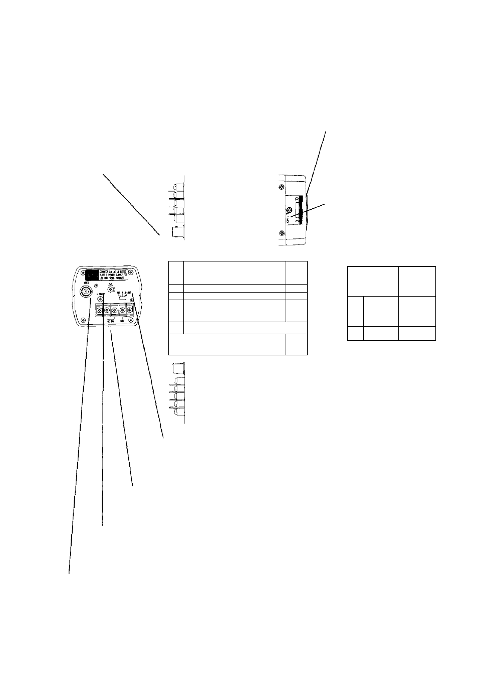
Video (BNC) Output Terminal;
Connect to monitor.
Top View
Rear view
Side View
TOSHIM cco COLO» oMPtA CCD
E
iPl-
!
124.J6 \
Bottom View
Focus Adjustment Dial:
Rotate this dial to appropriate
setting. Rotate towards "CS" side
when using a CS mount lens.
Rotate towards "C" side when
using a C mount lens. This Focus
Adjustment Dial can also be used
for back-focus adjusment.
Back Focus Set Screw;
This adjustment is for tightening
or loosening the Focus
Adjustment Dial. Before using
Focus Adjusment Dial, this set
screw should be loosened. After
using the Focus Adjustment Dial,
this screw should be tightened.
Front View
'T7
Ì )
q
70
' Auto-IRIS Terminal:
When using an auto-iris it needs
to be connected to this terminal.
Camera Mount-This 1/4 X 20
threaded hole if for use when
mounting the camera.
Lens Control Switch:
AES:
(Auto-Electronic Shutter) Set for Manual Iris Lenses
Al; Set tor Video-type Auto-Iris Lenses
AI-AMP: Set for Direct or DC-Type Auto-Iris Lenses
AC power supply terminal:
Connect to 24V AC UL listed class 2
power supply
Level Adjustiment:
When using a Direct or DC-Type
Auto-Iris Lens, use this adjustment to
attain an appropriate video level.
V. Phase Adjusment:
Used when multiple cameras within a system
are out of phase. Refer to section two and
seven of the manual for more information.