Peration – Carrier T-326 User Manual
Page 11
9
T--326
U
NIT
O
PERATION
2.1 OPERATING INSTRUCTIONS
Before attempting to operate the system, power must be available
from the vehicle battery. If the engine is not running, start the
engine. Most systems will not operate unless a signal is received
to the controller from the vehicle ignition.
Carrier Transport Air Conditioning system’s can be supplied with
two different type manual controls. the Standard Manual Control
and the Florida Control
1
2
3
4
5
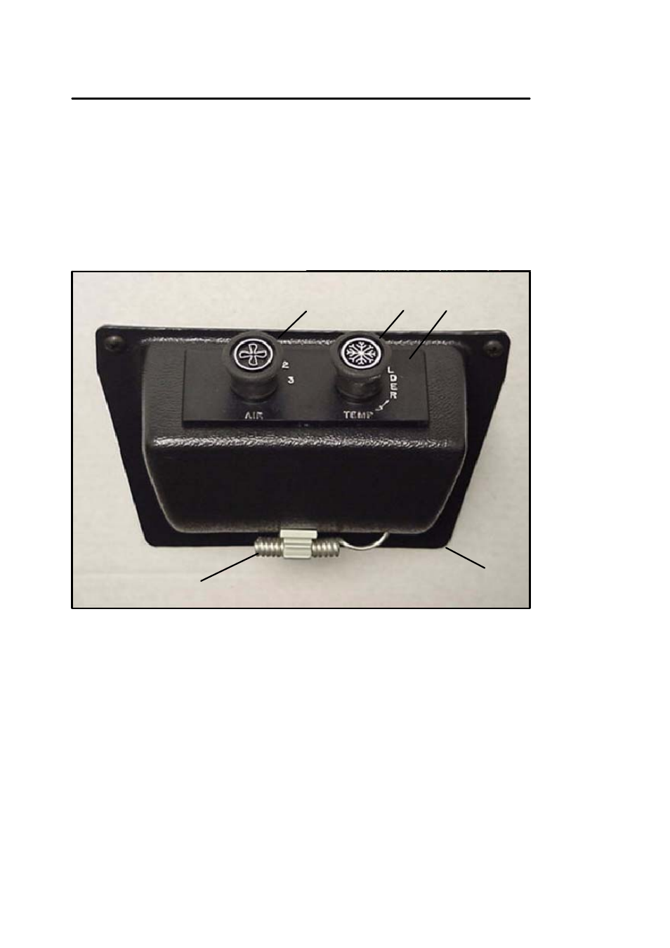
1 Control Panel Housing
2 Nameplate (Switch
Mounting)
3 Thermostat Control
4 Fan Speed Switch
(3 Speed or Variable)
5 Ambient Air Sensor
(Thermostat)
Figure 2-1 Drivers Control Panel -- Standard
2.2 DRIVER’S CONTROL PANEL -- STANDARD
The standard Drivers Control Panel (See Figure 2-1), consists of
an evaporator fan speed switch (three speed or variable) and an
adjustable thermostat. The drivers control panel is normally located
within easy reach of the driver. On larger bus applications there
could be two separate air conditioning system driver control panels.
One for each system.