Brining and brine rinse cycles, Backwash cycle – Kenmore 625.34847 User Manual
Page 25
Attention! The text in this document has been recognized automatically. To view the original document, you can use the "Original mode".
SECTION 5
SERVICE TECH. INFORMATION
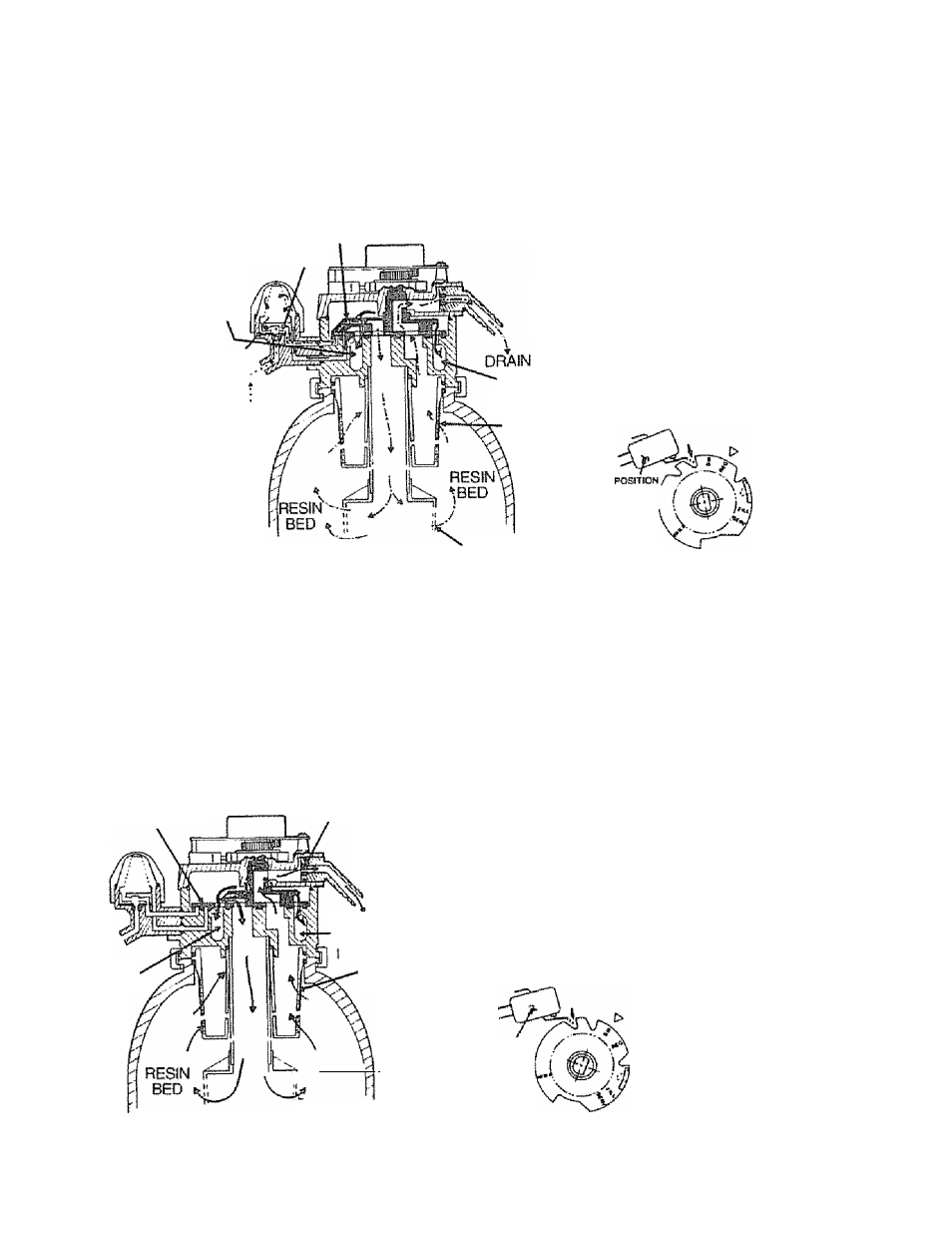
5C. WATER FLOW THROUGH THE SOFTENER VALVE
BRINING AND BRINE RINSE CYCLES
ROTOR & DISC
VENTURI
VALVE
OUTLET
(BYPASS HARD]
WATER)
NOZZLÉ
BRINE
FROM SALT
STORAGE
TANK
VALVE INLET
(HARD WATER)
YOP
distributor
SW itCH
BOTTOM
After fill, timer/switch action allows the motor to turn the rotor and disc into BRINING
position. Water flow is directed to t!ie nozzle Suction, created by the nozzle and venturi,
draws brine from the salt storage tank and injects it into the resin bed via the bottom
distributor Flow continues out the top distributor and to the drain, Hard water is available
at the valve outlet.
When die brine valve doses to end brine draw, water flow continues in the same
directions to slowly RINSE brine from the resin bed and to the drain.
BACKWASH CYCLE
ROTOR & DISC
FLOW PLUG
VALVE
OUTLET
DRAIN
VALVE
NLET
TOP
DISTRIBUTOR
DCCiK! 3
t ........... .............'ll ric!.wll' ■
BED
\ BOTTOM
DISTRIBUTOR
Timer/switch action again allows the motor to turn the
rotor
&
disc to place the valve in BACKWASH, stopping
water flow to the nozzle. Water is routed down and out the
bottom distributor, up through the bed, and out the top
distributor to the drain. The fast flow (controlled by a flow
plug in the drain fitting) flushes dirt, sediments, iron
deposits, remaining brine and hardness to the drain.
POSITION
SWITCH
25