Antl-tfp brackets installation instructions, Important safety warning, Anti-tip brackets installation instructions – Kenmore 5303304549 User Manual
Page 16
Attention! The text in this document has been recognized automatically. To view the original document, you can use the "Original mode".
Antl-Tfp Brackets
Installation Instructions
IF THE RANGE IS EVER MOVED TO A
DIFFERENT LOCATION,
the anti-tip
brackets must also be moved and '
installed with the range.
Tools Required:
5/16" Nutdriver or Flat Head Screwdriver
Adjustable Wrench
Electric Drill & 3/16“ Diameter Drill Bit
3/16* Diameter Masonry Drill Bit
(if installing in concrete)
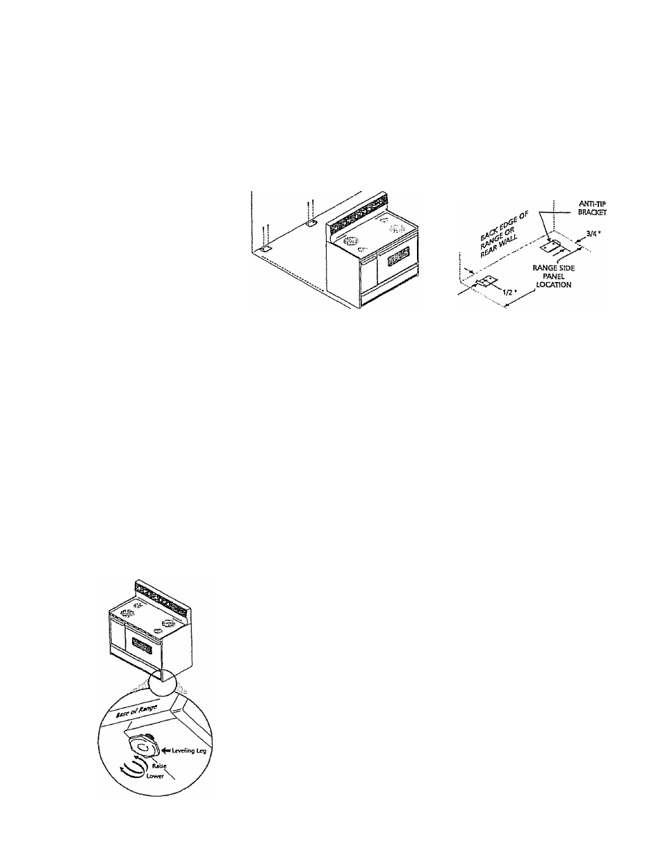
Figure 1: LeveUng Leg Instructions
Important Safety Warning
To reduce the risk of tipping of the range, the range must be secured to the floor
by properly installed anti-tip brackets and screws packed with the range. Failure to
install the anti-tip brackets could allow the range to accidentally tip over if excessive
weight is placed on an open door or if a child dimbs upon it. Serious injury might
result from spilled hot liquids or from the range itself. Refer to the instructions below
for proper installation.
AWn-tlP
BRACKET
Anti-Tip Brackets Installation Instructions
The brackets attach to the floor at the back of the range to hold both rear leg
levelers. When fastening to the floor, be sure that the screws do not penetrate
electrical wiring or plumbing. The screws provided will work in either wood or
concrete.
1. Unfold the paper template and place it flat on the floor with the back and side
edges positioned exactly where the back and sides of range will be located when
installed. Use the illustration above to locate the brackets if a template is not
available.
2, Mark on the floor the location of the four mounting holes shown on the
template. For easier installation, 3/16" diameter pilot holes, a 1/2" deep can be
drilled into the floor.
3, Remove the template and place the brackets on the floor with the turned-up
flange to the front. Line up the holes in the brackets with the marks on the floor
and attach with the screws provided. The brackets must be secured to a solid
floor, if attaching to a concrete floor, first drill 3/16" diameter pilot holes using
a masonry drill bit,
4. Level the range if necessary by adjusting the four leg levelers with a wrench, See
Figure 1, side box. A minimum clearance of 1/8“ is required between the
bottom of the range and the rear leveling feet
5., Slide the range into place making sure the rear legs are trapped by the ends of
the brackets- The range may need to be shifted slightly to one side as it is being
pushed back to allow the rear legs to align with the brackets ,. Remove the lower
panel or storage drawer to inspect the brackets, or grasp the top rear edge of
the range and carefully attempt to tilt it forward to make sure the range is
properly anchored,
16