Direct wire, Power supply cord or direct wire, Warning – Whirlpool 3406449 User Manual
Page 9: Page 9
Attention! The text in this document has been recognized automatically. To view the original document, you can use the "Original mode".
DIRECT WIRE
^WARNING
W
Electrical Shock Hazard
Turn power supply off before
connecting wires.
Use 10 gauge solid copper wire.
Electrically ground dryer.
Failure to follow these
instructions can result in death,
fire, or electrical shock.
1. Turn power supply off.
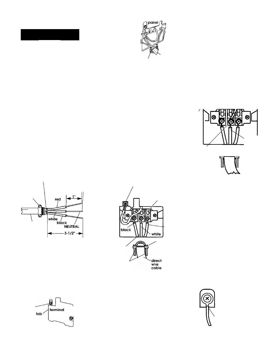
fcB Strip 3-1/2 inches of outer
covering from end of cabie. If using
three-wire cable with ground wire,
cut the bare wire even with outer
covering. Strip 1 inch of insulation
from the end of each insulated wire
(see Figure 17).
Bare wire cut short. Wire is not
used. Dryer is grounded
through direct wire cable.
3/4"
U.L.-listed
strain relief
to disconnect
box
wire stripped
of insulation
i 0-gauge
3-wire or,
10-gauge,
3-wire with
ground wire
(Romex)
Direct
wire
preparation
s
Figure 17
Shape the end of
each wire into a
"U" shaped hook
(see Figure 18).
u-shaped
hook
Figure 18
3
b
Remove hold-down screw and
terminal block cover.
external
ground
connector
hold-
/down
block cover / scfew
Figure 19
4
b
Attach 3/4" U.L.-
listed strain relief
(U.L. marking on
strain relieO to the
hole below terminal
box opening (see
Figure 20). Tighten
strain relief firmly to
cabinet so it is in a
horizontal position.
Place direct wire
cable through strain
relief.
rear
strain relief
(outside dryer)
Figure 20
O
b
Loosen or remove terminal
block screws. Connect the neutral
wire (white or center) of direct wire
cable under the center screw of
the terminal block. Place the hook
shaped end of the wire over the
terminal block screw with open side
of the hook facing to the right.
Squeeze hook end of wire together
to form a loop.
Connect the other two wires under
the outer terminal block screws.
Attach wires using the same
method as the neutral wire (see
Figure 21).
Tighten all terminal block screws
firmly.
Center wire MUST be connected to
center screw.
green with
yellow
stripes
(attached
at factory)
external ground
' connector
center
screw
(neutral)
center lead
must be
connected
to center
screw
strain
relief
red
strain
relief
Figure 21
6
b
Tighten strain relief screws.
# B Insert tab of terminal block
cover into slot of the dryer rear
panel (See Figure 19). Secure
cover with hold-down screw.
Power Supply Cord
or Direct Wire
Where local codes DO NOT
permit connecting the frame-
ground conductor to the
neutral (white) wire:
1 a.
Turn power supply off.
2a.
Complete Power Supply Cord
Steps 2-3, Page 7 or Direct Wire Steps
2-4, Pages 7-8.
external ground
connector
neutral ground
wire
(green/yellow
striped wire)
V
separate
copper
ground
wire
grounded
to a metal
cold water
pipe.
center screw
(neutral)
.center lead
must be
connected
to center
screw
Figure 22
3a.
Remove the neutral ground wire
(green/yellow striped wire) from
external ground connector screw.
Remove center terminal block screw
and fasten neutral ground wire to
screw (see Figure 22).
4a.
Complete Power Supply Cord
Steps 4-6, Page 7, or Direct Wire Steps
5-7, Page 8.
5a.
After reattaching the terminal
block cover, connect separate
copper ground wire from external
ground connector to grounded
metal cold water pipe. Contact a
qualified electrician to assure that
ground path is adequate (see Figure
23).
terminal
block cover
separate copper ground
wire connected and
grounded to a grounded,
metal, cold water pipe
Figure 23
Page 9