Carl Goldberg GPMA1967 Sr. Falcon ARF User Manual
Page 16
16
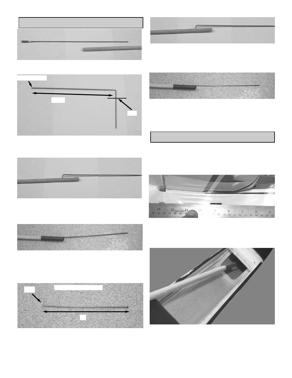
RUDDER PUSHROD
1.
Remove the metal clevis from the end of a 1.5
x 25cm wire.
Threaded end
8”
1/2”
2.
Measure, starting from the threaded end, back
8” and make a 90 degree bend.
Cut the wire 1/2” past the bend.
3.
Insert the wire into the hole in the wood
pushrod and push down into the groove.
Glue the wire to the wood pushrod using
medium CA glue.
4.
Slide the heat shrink tubing over the pushrod
and shrink using a blow drier.
Glue the tubing to the wood pushrod using
thin CA glue.
This finishes one end of the rudder pushrod.
1/2”
6”
NON THREADED WIRE
5.
Starting at the unthreaded end of the 1.5mm x
25cm wire, bend the last 3/8” up at a 90
degree angle.
Measure the length of the wire 6” from the
bend and cut the wire.
6.
Insert the wire into the hole in the wood
pushrod and push down into the groove.
Glue the wire to the wood pushrod using
medium CA glue.
8.
Slide the heat shrink tubing over the pushrod
and shrink using a blow drier.
Glue the tubing to the wood pushrod using
thin CA glue.
This finishes the rudder pushrod.
INSTALLING PUSHRODS
1.
Collect the following parts
(1) Elevator Pushrod
(1) Rudder Pushrod
(1) Fuselage
2.
Find the hole under the stabilizer on both
sides of the fuselage.
Cut the covering over each of the push rod
exit holes.
3.
Insert the pushrods into the fuselage through
the wing saddle area.