Top view float installation – Carl Goldberg GBGQ1296 User Manual
Page 5
WATER PROOFING.
We have found other than the floats
are absolutely water proof, the plane need
only be water resistant. For example, you
should use a hooded exit guide for the the
pushrod. And the fit between the wing and
the fuselage should be tight to keep the
water spray out( a seal of silicone caulk
works well.
In fresh water flying if you “dunk” and get the radio wet, generally just drying it out quickly is enough. If
not then it should be sent to be serviced.
In salt water flying you must be more careful as salt water is very corrosive. After each flying session
rinse exposed parts with fresh water then dry and oil metal parts that may rust. It is also a good idea to wrap
the receiver and battery in plastic bags, you can also place your servos in plastic bags.
STRUT ASSEMBLY AND MOUNTING
Before installing the floats, refer to sketches on these pages to familiarize with the proper float set-up
and mounting.
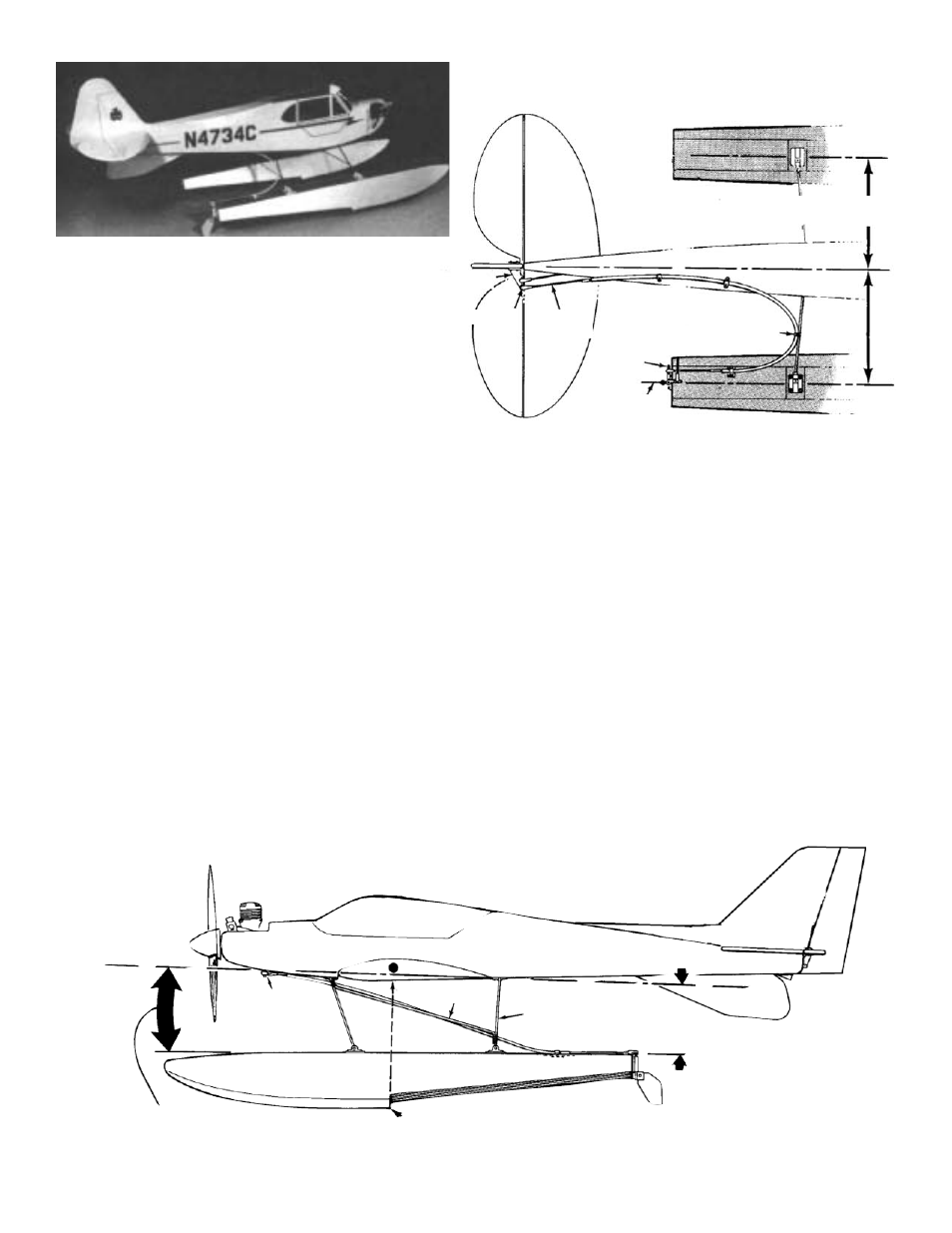
The placement of the float step in relation to the balance point (CG) is also important.To start with, we
recommend that the float step be near the balance point (CG). We have found that having the step slightly
ahead of the CG (1/2”) works better. And when the step is behind the balance point the plane tends to “stick”
to the water slightly.
Another important relationship is the angle that the floats are mounted at. Generally, the top of the
float and the bottom of the wing should be parallel. Because the Cub has basically a flat - bottom airfoil, this
relationship yields a slightly “positive” relationship to the float. If you add positive angle( lower the front of the
float)you should find the plane more willing to lift off from the water, but might tend to “porpoise” on landing.
Conversely, if you lessen this angle the model might tend to “stick” to the water but the landings should be
fine.
TOP VIEW
FLOAT INSTALLATION
5
SEMI OR FULL SYMMETRICAL WING
NOSE GEAR
STEERING OPTION
SIDE BRACE
BEND NEW STRUTS
FROM 5/32” WIRE
OPTIONAL
VENTRAL FIN
THE STEP SHOULD BE POSITIONED AT OR
SLIGHTLY AHEAD OF THE BALANCE POINT
FOR SEMI - OR FULL - -SYMMETRICAL WING,
MOUNT THE FLOATS SO THE WING IS AT A
GREATER ANGLE OF ATTACK
FLOATS MUST PARALLEL
MODEL CENTER LINE
TIE TO REAR STRUT
STEERING
ARM
WATER
RUDDER
THREADED
ROD
SNAP LINK
AIR RUDDER
CONTROL HORN
FLOAT OPTION TIGER 2