C&D Technologies RS-937 RDB Rack User Manual
Page 5
AdditionAl Assembly instructions
for eArthquAke Protected (eP) rAcks
7
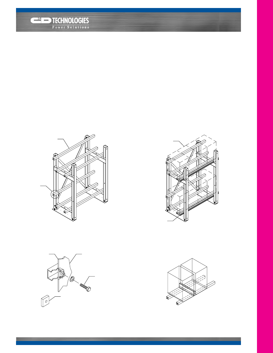
EP Rack Assembly (Continued): Install all back
restraint rail(s) and cover(s). See Figure 6. If installing a
rack to hold either a JC or XTJ battery system, the provided
spacer block must be installed between the restraint rails and
the frame. See Detail 3. Position front restraint rail and cover
temporarily next to front support rail prior to installing cells. DJ
Series battery racks to utilize lower set of restraint rail holes to
avoid interference with the handles.
8
Cell Installation Procedure: If not instructed otherwise,
install cells starting at the center of the bottom row and,
working out to each end, leave a half inch space between
cells. For EP racks, use spacers between cells as supplied.
Do not use oil or grease as lubricants
. Instead a small
amount of water or unscented talcum may be applied to the
rail cover to help reduce friction. For rows having an odd
number of batteries, the center of the first battery installed
will match the center of the row. For rows having an even
number of batteries, a cell space will coincide with the center
of the row.
Pay attention to polarities and terminal placement
.
Refer to the battery’s Installation and Operating Instruction
manual for more details. All cells should be pushed back
against back restraint rail and cover. Up to 1/8” gap between
restraint rail and cells is acceptable. Repeat this procedure
for remaining steps and tiers, working upward. See Figure 7.
Figure 7a. Cell Spacer Detail (L-Series)
Front Restraint Rail
and Cover (loose)
Figure 7. Cell Installation
Battery Units
Back Restraint
Rail to Frame
Connection.
See Detail 3.
Figure 6. Initial Step For EP Rack
Back Restraint
Rail and Cover
Frame
Detail 3. Frame and Restraint Rail(s)
(Reverse View)
3/8-16 Hex Bolt,
Lock Washer and
Serrated Nut
Back Restraint
Rail and Cover
1/2” Spacer
Block. Used for
“J” Series Only