Braeburn 169000 User Manual
Indoor air quality products, Installation instructions, Application precautions installation
INSTALLATION INSTRUCTIONS
MODEL 169000
AIR FILTER GAUGE
APPLICATION
PRECAUTIONS
INSTALLATION
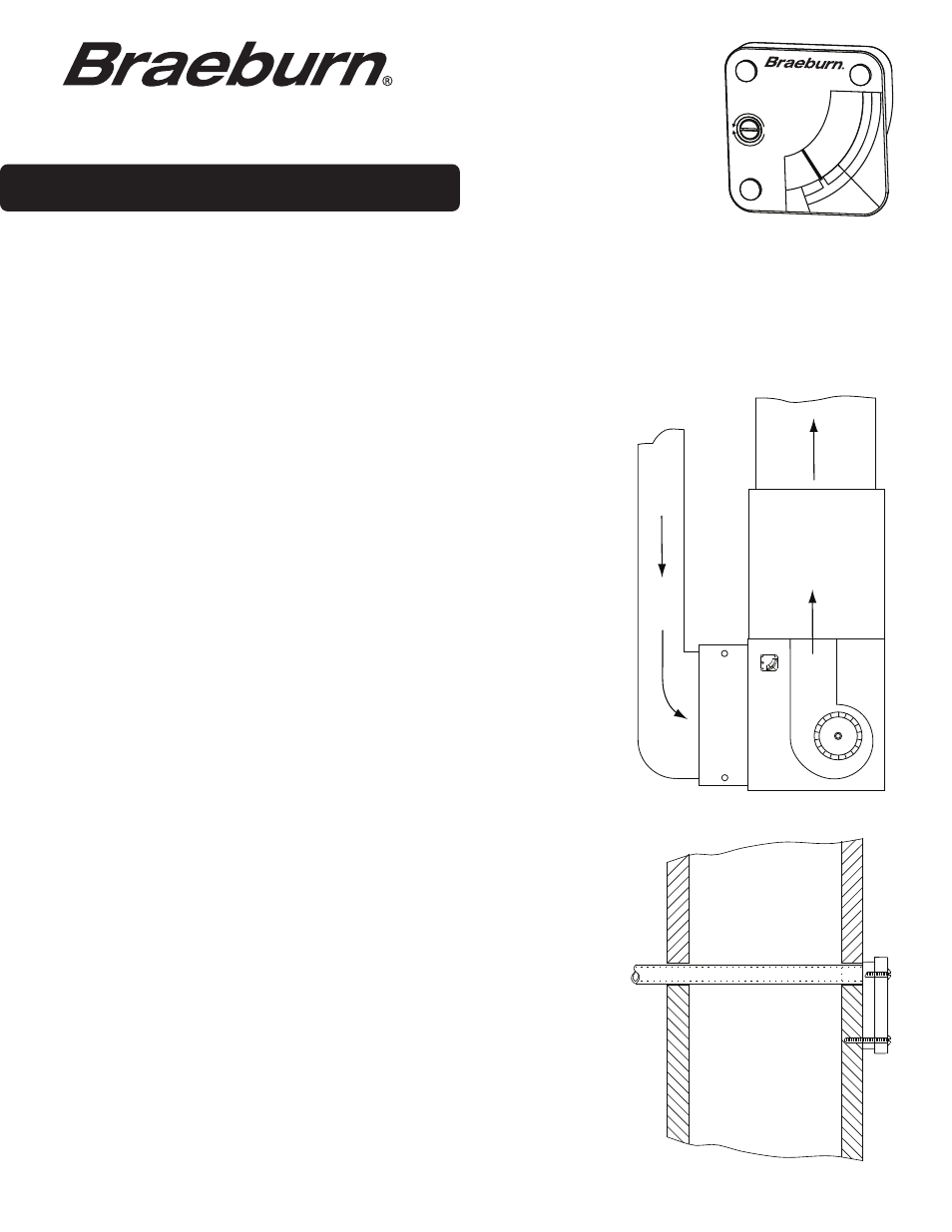
(Figure 1)
AIR
FILTER
BLOWER
RETURN
AIR
GAUGE
INSTALL CLEAN
FILTER, RUN
BLOWER AND
ADJUST GAUGE
POINTER TO
CLEAR AREA
IN CENTER
OF GREEN
UP
DOWN
FILT
ER
IS
CL
EA
N
C
H
A
N
G
E
F
IL
T
E
R
AIR FILTER GAUGE
Indoor Air Quality Products
AIR FILTER GAGE
INSTALL CLEAN
FILTER, RUN
BLOWER AND
ADJUST GAGE
POINTER TO
CLEAR AREA
IN CENTER
OF GREEN
UP
DOWN
FILT
ER
IS
CL
EA
N
C
H
A
N
G
E
F
IL
T
E
R
The 169000 Air Filter Gauge provides a visual indication of the need to replace the air filters in forced air heating and cooling
systems. The gauge is installed between the blower and the filter where a slight vacuum exists due to the air flow resistance
of the air filter. Air flowing into the gauge, around the calibration screw, lifts a vane in proportion to the negative pressure in
the blower compartment. As the air filter loads, the vacuum increases, raising the vane to indicate a filter change
is necessary.
The gauge may be calibrated in a negative pressure range from 0.1 to 0.4 inch w.c. When properly calibrated in this range a
vacuum increase of 0.10 to 0.15 inch w.c. will indicate a filter change is necessary.
The installer should be an experienced service technician. When drilling the hole
in the blower compartment extreme care should be taken not to damage
components within the heating or cooling system.
OPTIONAL REMOTE INSTALLATION
(Figure 2)
FIELD SUPPLIED:
One (1) piece of 5/16” (inside diameter) vinyl tubing up to 10
feet in length, and three (3) #4-24 x 1” screws.
1. Select a location on the blower compartment between the air filter and the
blower and drill a 7/16" diameter hole. Insert one end of the vinyl tubing
about 2" into the hole.
2. On a wall, enclosing the furnace room for example, mark a position where
the filter gauge can be easily seen and is within reach of the vinyl tube.
3. Drill a 1/2" diameter hole through the wall and feed the vinyl tube through
the hole. Keep overall length of tubing used as short as possible.
4. Push the three plastic retainer clips out from the back of the gauge with a
blunt tool. They will be replaced with the three #4-24 x 1" screws included.
5. Push the vinyl tubing over the pressure sensing tube of the gauge and
move the gauge back against the wall in a level position. Drill three 3/32"
diameter holes through the gauge holes. Drive the three screws to hold the
gauge in place. Do not overtighten.
6. See “CALIBRATION”.
Figure 1
Figure 2
1. The gauge must be located where it can sense pressure conditions in the
blower compartment between the filter and the blower. Select a location on
a vertical surface enclosing the blower compartment and drill a 3/8" hole.
2. Remove the protective paper from the foam adhesive strip on the back
of the gauge.
3. Mount the gauge in a level position with the pressure sensing tube
projecting into the blower compartment.
4. See “CALIBRATION”.