Braeburn-spc-back, Modulating bypass setup electrical connections – Braeburn SPC User Manual
Page 2
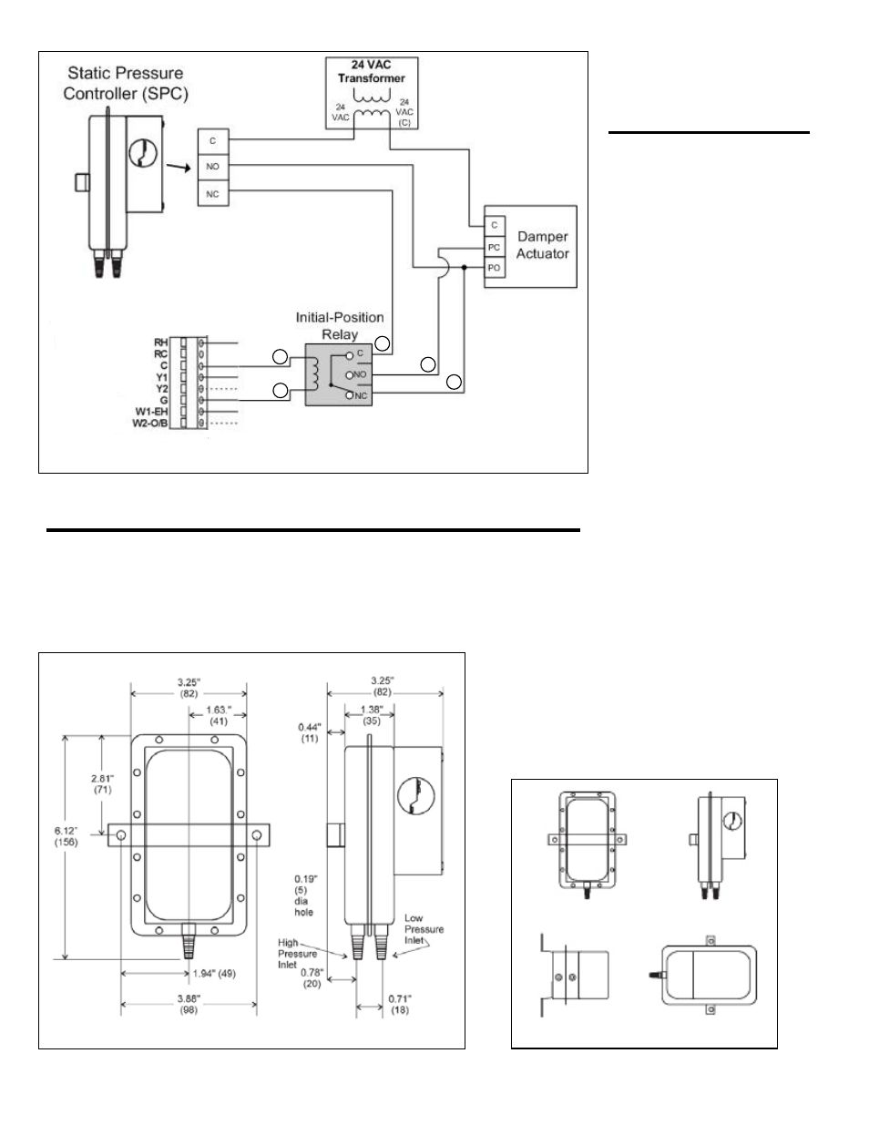
Figure 1 – Wiring Diagram
Modulating Bypass
Setup
Electrical Connections
Figure 2 – Dimensions
Figure 3 – Mounting
With all zones calling (all dampers
open), make certain that the fan is
in the highest speed that will be
used when the sysem is running.
Turn the set screw clockwise ¼
turn each time until the bypass
damper motor is obviously running
closed. If the bypass damper
should reverse and start opening,
turn the set screw another ¼ turn
and repeat until the damper is
closed. Next, slowly turn the set
screw counter clockwise until the
bypass damper motor start to run
open. Immediately, turn the set
screw clockwise until the damper
motor starts to close again.
The goal is to set the bypass
damper so that it is barely staying
closed when all zones are open.
This will cause the bypass damper
to open if supply dampers close
and the plenum pressure goes up.
As dampers open and/or close
during operation, the static pres-
sure sensor will sense a pressure
change and make the Power
Open/Power
Close
bypass
damper move to maintain the
same pressure in the plenum that
was established when all zone’s
were open.
Braeburn Systems LLC, 2215 Cornell Avenue, Montgomery, Illinois 60538, U.S.A.
Telephone (866) 268-5599, Facsimile (866) 268-3611
Before pressure is applied to the diaphragm, the switch contacts on the SPC will be
in the normally closed (NC) position. This snap switch has screw top terminals with
cup washers. Wire according to
Figure 1.
4
3
1
2
5