Data interface cable pin-out configurations – Cisco 545 Serial User Manual
Page 41
2-21
Installation and Upgrade Guide for Cisco Unified Videoconferencing 3545 PRI Gateway and 3545 Serial Gateway Release 5.5
OL-14912-01
Chapter 2 Installing the Cisco Unified Videoconferencing 3545 Gateway
Serial Gateway Cable Connections and Pin-outs
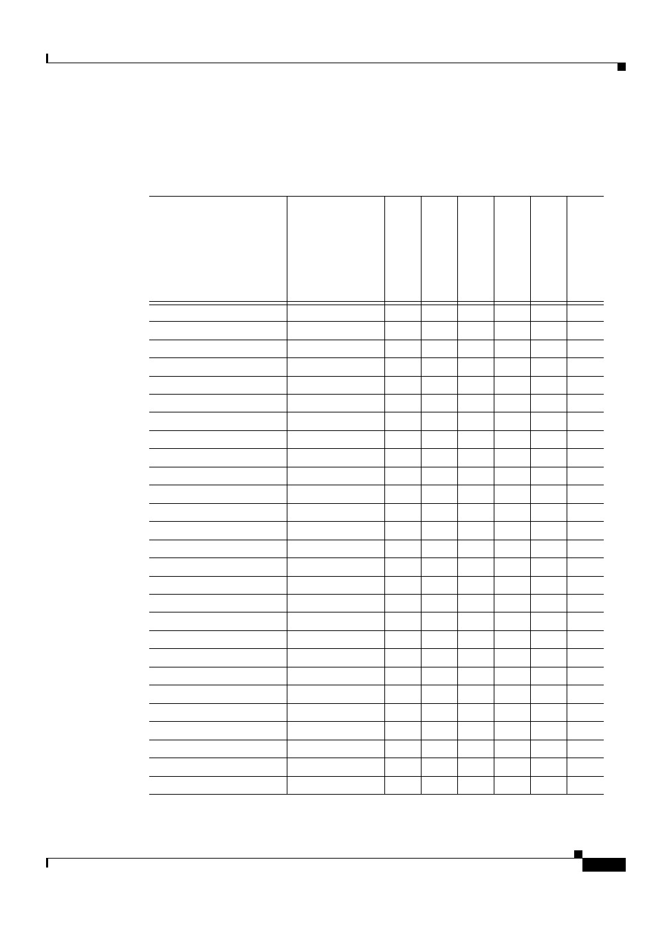
Data Interface Cable Pin-out Configurations
describes the data interface pin-out configuration for the serial gateway cables.
Table 2-7
Serial Gateway Data Interface Cable Pin-out
Signal Name
Mnemonic
KIV
-7 (DB-37
)
DTE only
EIA-4
49 (DB-37)
EIA-5
30 (DB-25)
EIA-5
30 LOS (DB-25)
DTE only
EIA
-53
0A
LO
S (DB
-25
)
DTE only
V
.35
(M-34)
Shield
—
1
1
1
1
1
A
Transmit Data
TXD A
2
4
2
2
2
P
Transmit Timing
TXC A
15
5
15
15
15
Y
Receive Data
RXD A
3
6
3
3
3
R
Request To Send
RTS A
4
7
4
4
4
C
Receive Timing
RXC A
17
8
17
17
17
V
Clear To Send
CTS A
5
9
5
5
5
D
Data Set Ready
DSR A
6
11
6
6
6
E
Data Terminal ready
DTR A
20
12
20
20
20
H
Carrier Detect
DCD A
8
13
8
8
8
F
Terminal Timing
TT A
24
17
24
24
24
U
Signal Ground
—
27
19
7
7
7
B
Transmit Data
TXD B
14
22
14
14
14
S
Transmit Timing
TXC B
12
23
12
12
12
AA
Receive Data
RXD B
16
24
16
16
16
T
Request To Send
RTS B
19
25
19
19
19
—
Receive Timing
RXC B
9
26
9
9
9
X
Clear To Send
CTS B
13
27
13
13
13
—
Data Set Ready
DSR B
22
29
22
22
—
—
Data Terminal ready
DTR B
23
30
23
23
—
—
Carrier Detect
DCD B
10
31
10
10
10
—
Terminal Timing
TT B
11
35
11
11
11
W
Local Loopback
LL
—
10
18
—
18
L, K
Remote Loopback
RLB
—
14
21
—
21
N
Loss of Sync
LOS unbalanced
31
36
—
—
—
—
Loss of Sync
LOS A
—
3
—
18
—
—
Loss of Sync
LOS B
—
21
—
21
—
—