General wiring instructions – American Access Systems Touch Plate Reader - 11-65000 User Manual
Page 22
Page 22 American Access Systems / Security Brands, Inc.
CAUtIon SHoULd Be tAKen not to toUCH CIrCUIt BoArd or eLeCtronIC CoMPonentS PrIor to InStALLAtIon to
AVoId eLeCtro-StAtIC dISCHArGe (eSd) dAMAGe.
wArnInG
do not APPLY Power to UnIt UntIL
ALL ConneCtIonS Are MAde And CHeCKed
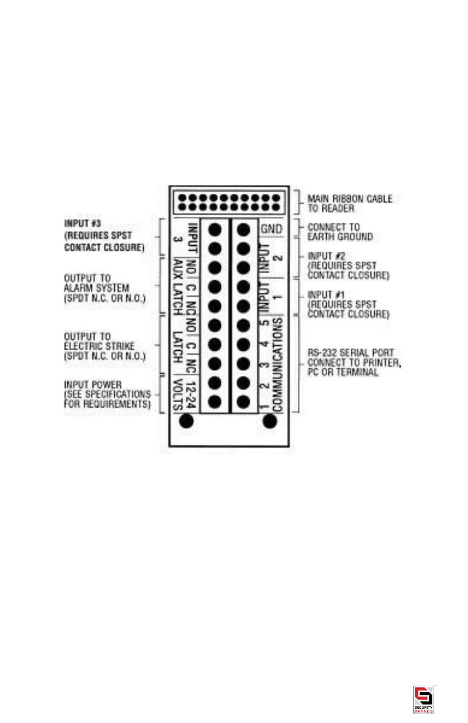
GenerAL wIrInG InStrUCtIonS
For ease of installation and servicing, the 11-65000 is provided with a terminal board which is connected to the main
unit via a ribbon cable and connector. The screw terminals on the circuit board will accept wire gauges #16 through
#24, solid or stranded. Strip approximately 5/16” (8mm) of insulation, insert into the appropriate hole, and tighten
with a small screwdriver. Tinning is strongly recommended for stranded wires (see Figure 2 for proper terminations).
Arrange a cable drip loop on all exterior installations.