AAF International SAH User Manual
Page 8
8
3.4 General Filter System Installation Procedure
CAUTION
AAF offers particular optional modifications that must be included
if the Side Access Housing is to be located outdoors where it will
be exposed to the weather and sunlight. These include a weather
cover, special door hardware, and modified and specially sealed
panel joint construction. Make sure that the weather proof option
has been included on the purchase order before installing the
equipment outdoors.
3.4.1 Installing the Side Access Housing (SAH): Keeping the
SAH on its shipping pallet, move it to its final installation location.
Remove the restraints that secure the SAH to its pallet and remove
any wrapping or packaging material.
! WARNING: The housing top will not support the weight of the
unit. Any attempt to support the housing from the top may result in
serious equipment damage and severe personal injury. Do not walk
on the top of the unit or use the top for storage of materials.
3.4.2 Locating, Mounting, and Supporting the Side Access
Housing (SAH): Locate the SAH in its final installation location.
The support surface under the base of the frame shall be level,
smooth, clean, and dry. The location shall not be subject to
standing water or flooding. The circumference of the housing
base shall be fully supported. Adjust the supports so that the
base is level in all directions.
Anchoring the Housing: A suggestion for anchoring the
standard housing is provided in Figure 2. If an optional channel
base has been ordered the lower flange of the channel will
include mounting holes. See the channel base photograph
referenced in paragraph 1.2.3 for details.
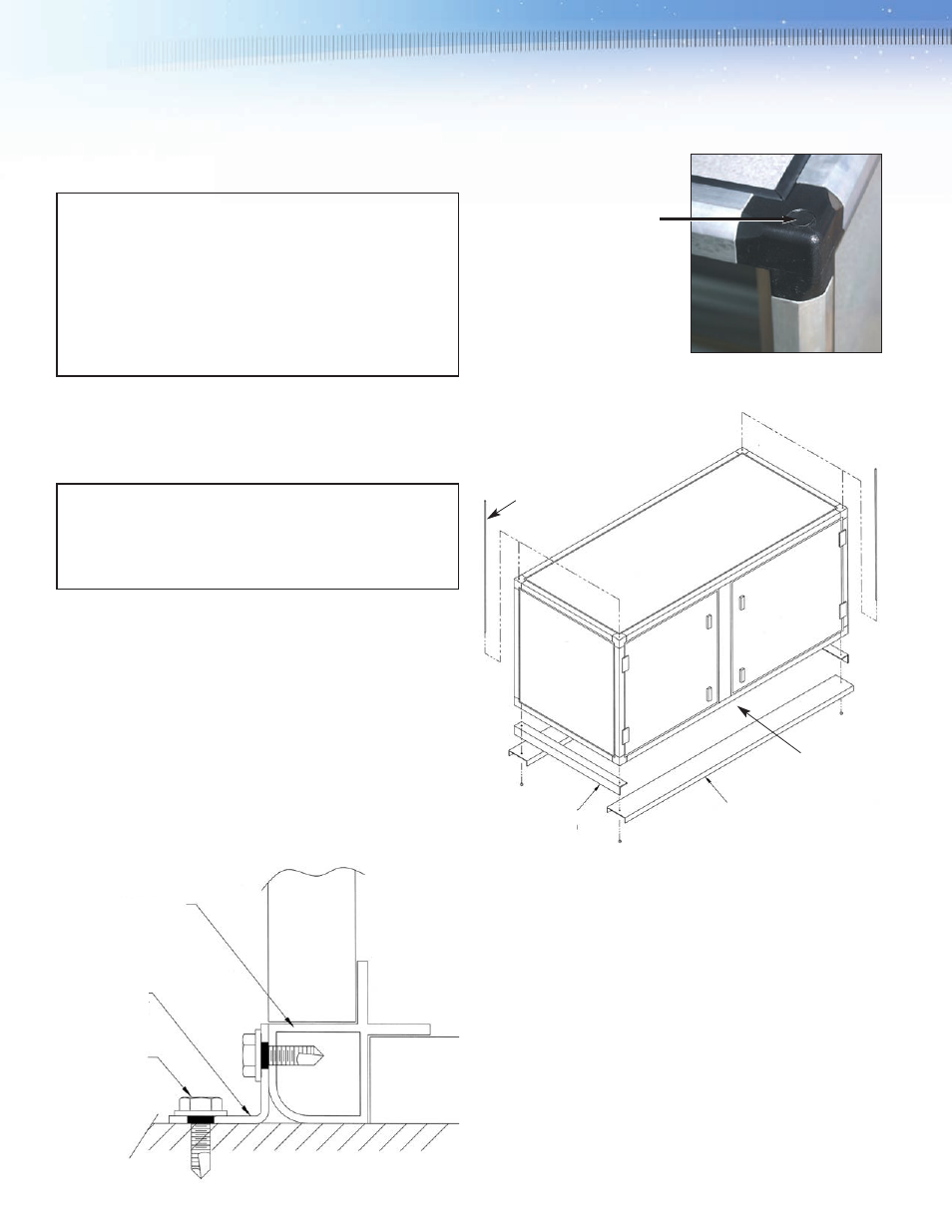
Hanging the Housing from
a Ceiling: The Side Access
Housing has circular
knockouts on the corner
connections. Remove the
knockouts and suspend the
housing using
1
⁄
2
" maximum
diameter threaded rods,
hardware and a cradle
which includes C-channel
and angle supports as
suggested in Figure 3 below. Again, make sure that the
circumference of the housing base is fully supported.
In all cases the foundation or support cradle and supporting
structure shall be designed for each specific installation by a
qualified professional engineer.
Provision of anchoring hardware, support cradles, or any other
supporting component will be the responsibility of the installer or
others. These items will not be supplied by AAF unless noted
specifically in the AAF quotation and in the accepted customer
purchase order.
3.4.3 Connection of Inlet and Outlet Ducts: Inlet and outlet ducts,
when required, shall be connected to the inlet and outlet faces of
the housing as shown in Figure 4.
Figure 2
Aluminum Frame
Angle Support Clip,
by others
Anchor Bolt,
by others
Figure 3
Angles on Both
Ends Required
C-channels are Required
on Both Sides
Intermediate
lateral supports
may be required
Threaded Rods
Shim as Required to Evenly Support the Housing Base Circumference