Kistler-Morse KM Junction Box User Manual
Page 12
97-1076-01 Rev. B
8
www.kistlermorse.com
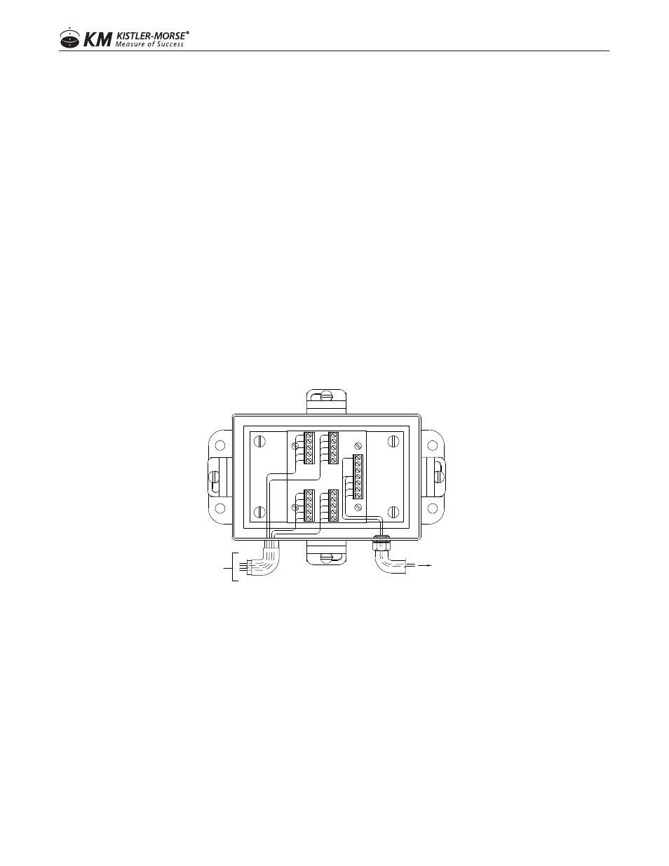
WIRING SENSORS TO JUNCTION BOX (FULL BRIDGE: KM LD3XI, LD3XIC, TC-1)
1. Install liquid tight fittings.
2. Seal fittings with Sikaflex or electrical grade sealant.
3. Thread the sensor cable through the desired conduit fitting; see Figure.
4. Estimate the required length of cable to terminal strip, allowing a little extra for strain relief. Cut the
excess cable.
5. Strip back 3 in. (76 mm) of the cable sheathing to expose the four wires and the shield inside. Strip back
1/4 in. (6 mm) of insulation from the end of each of the wires.
6. Connect the sensor wires to the selected TB2-5 terminals on the left side of the Junction Box:
Red or brown wire to +EX
White wire to +SIG
Black wire to -EX
Blue wire to -SIG
7. Perform Steps 3 through 5 for each sensor you wire to the Junction Box. Up to two sensors can be
wired to each terminal.
8. Replace the Junction Box cover, if not ready to begin wiring the Junction Boxes together.
WIRING JUNCTION BOXES TOGETHER AND TO CONTROLLER (FULL BRIDGE)
GUIDELINES
• One large hole for conduited installation: The large hole, which accommodates a 3/4 in. conduit fitting, is for
wiring the Junction Box to the other Junction Boxes and to the controller.
• Two large holes for non-conduited installation: The two large holes, which accomodates PG13.5 cable
fittings, are for wiring the Junction Box to the other Junction Boxes and to the controller.
• The following procedure assumes the conduit/cable trays have been installed.
• Seal all conduit fittings against water entry. Install drain holes at the conduit’s lowest elevation(s) to allow
condensation to drain.
FROM VESSEL LEGS
LOAD DISC CABLES
TO SIGNAL PROCESSOR
OR OTHER J-BOX
+EX
+SIG
-SIG
-EX
SH
SH
-EX
-SIG
+SIG
+EX
SH
-EX
-SIG
+SIG
+EX
SH
-EX
-SIG
+SIG
+EX
+EX
-EX
-SIG
+SIG
SH
-SNS
+SNS
FULL B
RIDG
E JUN
CTION B
OX
ASSY
63-1282-01
REV