Kistler-Morse KM Junction Box User Manual
Page 11
7
www.kistlermorse.com
97-1076-01 Rev. B
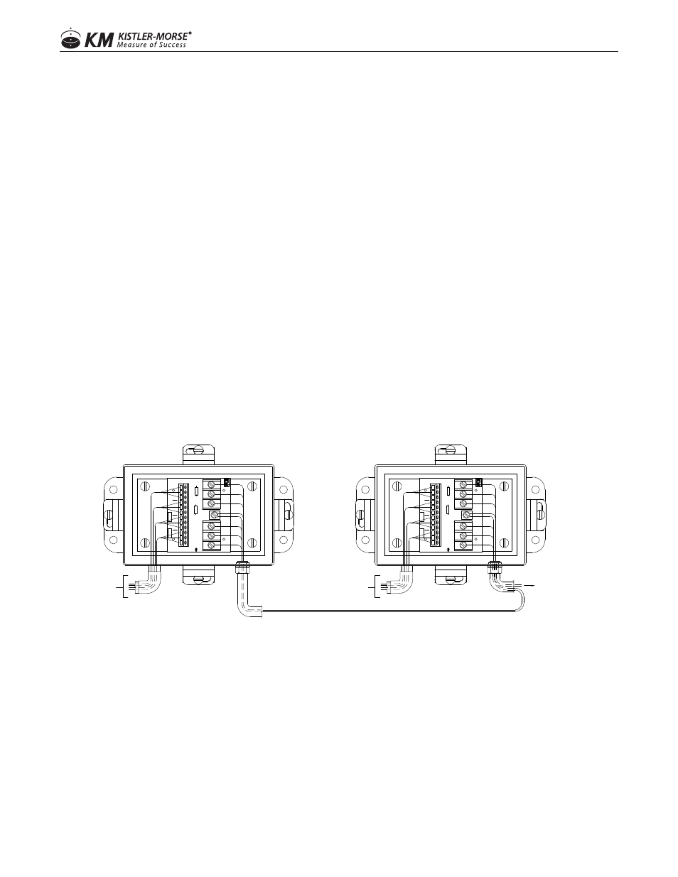
1. Remove the Junction Box cover.
2. Route the 3-conductor cable through the fitting into the junction box farthest from the controller.
3. Connect the wires from the cable to the TB3 terminal in the Junction Box.
Black wire to B Terminal
White wire to W Terminal
Red wire to R Terminal
4. Connect the cable shield wire to the Shield Terminal between TB1 and TB2.
NOTE: The shield terminal will not connect to anything; be sure to connect on the device side though.
5. Route the cable through the conduit/cable tray to the next Junction Box.
6. Estimate the required length of cable to the terminal strip, allowing for a little extra for strain relief. Cut
the excess cable.
7. Connect wires from the cable tothe TB1 Terminal in the Junction Box - see Step 3 above.
8. Route another 3-conductor cable through the fitting into this Junction Box and attach wires to the TB2
Terminal - see Step 3 above.
9. Repeat until all vessels are wired together.
10. Route the cable from the last Junction Box through the conduit/cable tray to the controller. Refer to the
controller manual for wiring diagarams required to wire the Junction Box to the controller. One vessel
takes up one channel in the controller; the channel shows the average value from all the sensors on the
vessel supports.
FROM VESSEL LEGS
LOAD DISC CABLES
LOAD DISC CABLES
FROM VESSEL LEGS
TO SIGNAL PROCESSOR
OR OTHER J-BOX
SENSO
R
A
TB3
TB2
SENSO
R
D
12
R
W
B
TP1
3
R
W
MADE IN U
SA
ASSY 63-1170-
SENSO
R
B
B
SENSO
R
C
REV.
R
W
R
W
R1
W
B
R
B
1
R2
NO ST
ANDA
RDIZA
TION
R
SHLD1
B
1
3
TB1
W
B
1
12
SENSO
R
D
R
W
B
TP1
TB2
3
R
W
MADE IN U
SA
SENSO
R
B
ASSY 63-1170-
SENSO
R
C
REV.
W
R
B
R
W
R1
TB3
R
B
W
SENSO
R
A B
1
R2
NO ST
ANDA
RDIZA
TION
SHLD1
B
1
3
R
TB1
W
B
1