Kistler-Morse KM Junction Box User Manual
Page 10
97-1076-01 Rev. B
6
www.kistlermorse.com
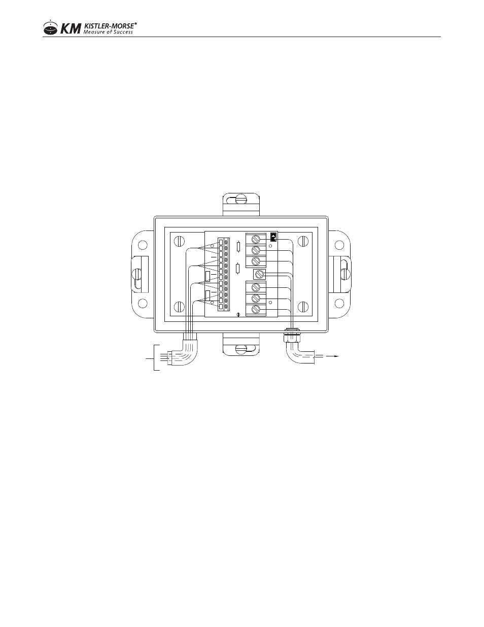
5. Strip back approximately 3 in. (76 mm) of the cable sheathing to expose the three wires inside. Strip
back 1/4 in. (6 mm) of insulation from the end of each of the wires.
6. Connect the wires from the sensor to the selected TB3 terminals; black wire to B terminal, white wire to
W terminal, and red wire to R terminal.
7. Perform Steps 2 through 6 for each sensor that needs to be wired to this particular Junction Box (up to
four)
8. Spread of generous bead of sealant (Sikaflex 1A polyurethane or Dow Corning RTV 738 or RTV 739)
around the water-tight fitting and the sides of the plug for each hole not being used. Screw a plug into
each hole.
9. Replace the Junction Box cover and screws if not ready to begin wiring them to ensure that no moisture
enters the Junction Box enclosure.
WIRING JUNCTION BOXES TOGETHER AND TO CONTROLLER (HALF BRIDGE)
GUIDELINES
• One large hole for conduited installation: The large hole, which accommodates a 3/4 in. conduit fitting, is for
wiring the Junction Box to the other Junction Boxes and to the controller.
• Two large holes for non-conduited installation: The two large holes, which accomodates PG13.5 cable
fittings, are for wiring the Junction Box to the other Junction Boxes and to the controller.
• The following procedure assumes the conduit/cable trays have been installed.
• Seal all conduit fittings against water entry. Install drain holes at the conduit’s lowest elevation(s) to allow
condensation to drain.
• Use Belden 3-conductor shielded interconnect cable or equivalent to wire Junction Boxes together and to
the controller. For lengths up to 1,000 ft ( 305 m), use 18-gauge Belden 8791 cable. For lengths from 1,000
to 2,000 ft (305 to 610 m), use 16-gauge Belden 8616 cable.
• When wiring cable to Junction Box terminals, strip back 3 inches (76 mm) of cable sheathing to expose the
3-conductor wires and shield wire inside. Strip 1/4 inch (6 mm) of insulation from the end of each of the
conductor wires.
OR OTHER J-BOX
TO SIGNAL PROCESSOR
FROM VESSEL LEGS
LOAD DISC CABLES
3
R
TB2
1
B
W
MADE IN USA
SENSOR D R
12
REV.
SENSOR C B
W
R
B
W
TP1
TB1
R1
3
W
R
1
B
R2
SENSOR B
ASSY 63-1170-
W
R
B
W
R
TB3
SENSOR A
1
B
NO ST
AND
ARDIZA
TION
SHLD1