9) thermostatic valve set up – Jaclo Thermostatic Valve, Rough - J-TH34 User Manual
Page 12
jaclo
industries | 129 Dermody Street Cranford, NJ 07016
p 908.653.4433 | 800.852.3906 f 908.653.1717 | 800.852.4133
JACLO.COM | PG 12
CREATED 5.2014
(6) System Check Continued
(7) Reinstall rough in shield
(8) Finished wall opening
A. Minimum opening size opening to operate check stops, removing thermostatic and diverter cartridges
is required.
B. See Fig. 1 for maximum finished wall opening.
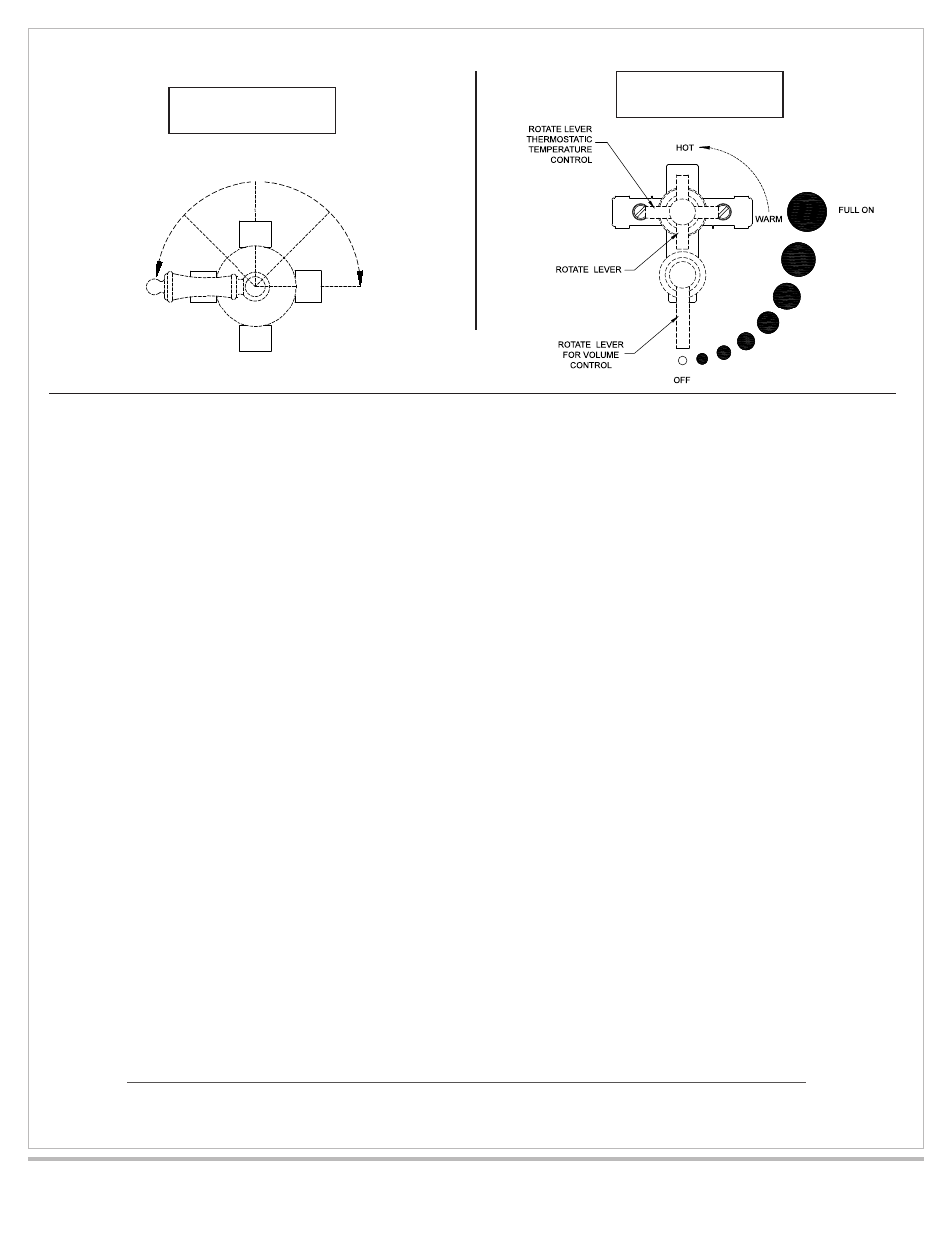
(9) Thermostatic valve set up
A. Remove rough in shield and discard if trim is to be installed after valve setup.
B. Remove max temp. tag and discard.
C. Screw sleeve onto thermostatic valve body until it bottoms on stop ring, to retain stop ring. See Fig. 5
D. Place diverter in off position and close volume control valves if used. See Fig. 8 for diverter operation
E. Open hot and cold check stops, see Fig. 5.
F. Open diverter to allow water flow, rotate thermostatic valve full counter clockwise and check water
temperature with thermometer. Factory setting should be 100° maximum. See Fig. 6.
G. Limit stop setup:
i. Remove limit stops, Fig. 5
ii. Open diverter to allow water flow, run water for 5 min. See Fig. 6.
iii. Measure water temperature while rotating spindle counterclockwise. Stop rotation at highest desired
water temperature to stabilize for one minute, confirm desired setting. See Fig. 5 & 6.
iv. Replace hot limit stop so leg is resting against stop ring. See Fig. 5
v. Rotate spindle gently clockwise until water is cold and spindle stops rotating.
DO NOT ROTATE SPINDLE PAST STOP POSITION. THIS WILL DAMAGE THE CARTRIDGE!
vi. Replace cold limit stop so leg is resting against the stop ring. See Fig. 5.
vii. Turn off diverter valve. See Fig. 6.
J-THVC12
J-20682
3 1/4"
3 1/4"
1/2" DIA.
3/8" DIA.
4"
4 1/2"
6 13/16"
A
PORT
C
PORT
AB ON
BC ON
B
ON
B
PORT
INLET
16 PT.
SPLINE
A ON
C ON