Holes to fix the mask level c c1 – Jaclo Gosh Concerto - 1730 User Manual
Page 4
jaclo
industries | 129 Dermody Street Cranford, NJ 07016
p 908.653.4433 | 800.852.3906 f 908.653.1717 | 800.852.4133
JACLO.COM
GOSH CONCERTO | PG 4
CREATED 5.27.10
ISTXX2492TK ING. 07.02.08. REV=00
ISTXX2492TK ING. 07.02.08. REV=00
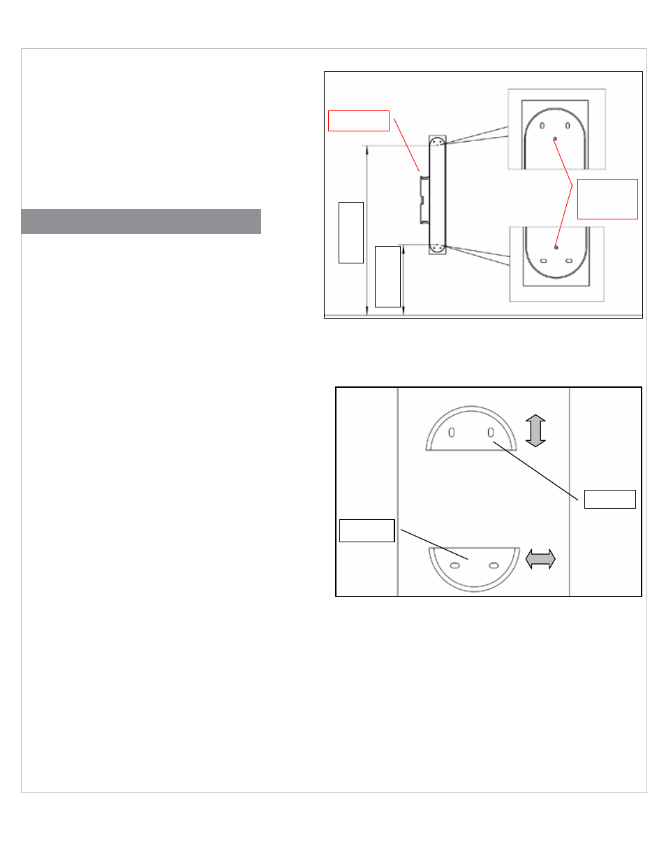
Holes to fix
the mask
Level
C
C1
ISTXX2492TK ING. 07.02.08. REV=00
ISTXX2492TK ING. 07.02.08. REV=00
Holes to fix
the mask
Level
C
C1
1 › Follow the instructions in Figure 1 to establish the height
at which the shower column is to be assembled. This
height can be obtained from the illustrative values in
the table according to your personal height or any other
desired height. Once the height of the column has
been established, find the corresponding value for “C1”
and/or “C” to fix the assembly template.
2 › Assemble the cardboard template (Figure 2) using the
value “C” for the upper fixation. Before fixing the lower
part of the template, using a level, make sure it is in the
vertical position
1 › Pre-fix the two brackets (C) and (C1) (Figures 2 and 4)
using four screws M6X70 (D) in the 4 anchors (A) previ
ously inserted in the wall (B) (Figure 4) and remove the
fixing template
2 › Assemble the column on the brackets, being careful not
to damage the outer finishing and making sure the
brackets are properly positioned.
If the brackets previously fixed on the wall prevent the
column from being correctly fixed, remove the column
and make the necessary adjustments
As indicated in Figure 3, it is possible to make a slight
adjustment of the position of the brackets. In particular,
loosen the screw which fixes the upper clamp to make
a small adjustment of the relative distance of both
brackets.
Act on the lower clamp to make a slight regulation in
the axial direction in order to assemble the column in a
perfectly vertical position
Connect the water mains (F) (Figure 4) to the two incom-
ing openings of the thermostatic mixer (E) (Figure 1)
3 › Position the body of the shower column (G) on the two
brackets (C and C1) previously fixed to the wall (Figure 4)
4 › Insert the stop knob (I) in the upper part (Figure 4-B)
5 › Fix the column by tightening the screw M8X16 (H) of the
lower part (Figure 4-A)
6 › Assemble the handshower to the water outlet (L) by
means of its flexible pipe (Figure 4)
FINISHING ASSEMbLy INSTRUCTIONS
ISTXX2492TK ING. 07.02.08. REV=00
ISTXX2492TK ING. 07.02.08. REV=00
Clamp C
Clamp C1
ISTXX2492TK ING. 07.02.08. REV=00
ISTXX2492TK ING. 07.02.08. REV=00
Clamp C
Clamp C1