Installation – Inovonics FA536 User Manual
Page 3
Installation
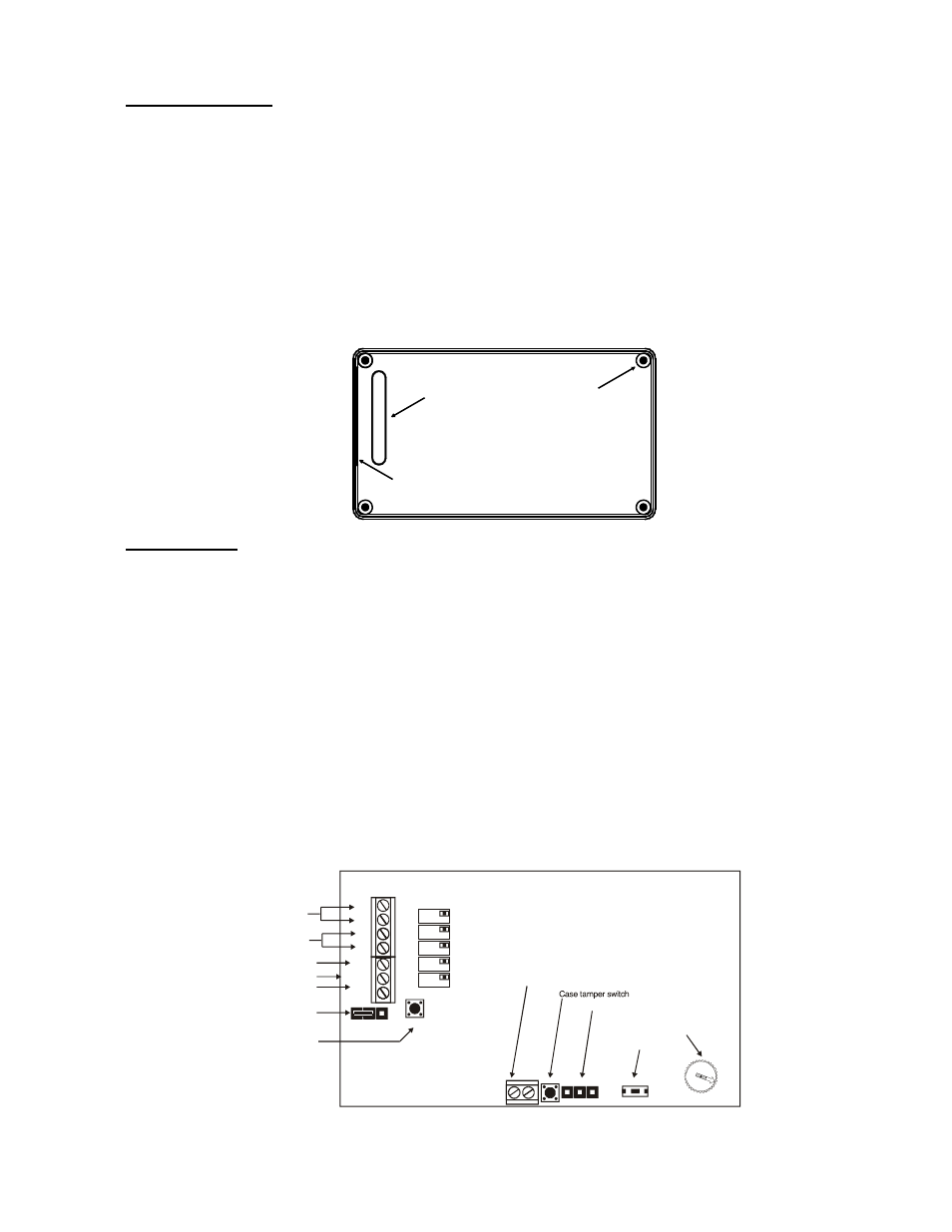
Mounting locators:
•
Locators should be mounted in locations indicated by the system designer.
•
Unless specifically instructed to do so by the system designer, do NOT mount
locators on metal surfaces or inside metal enclosures. Do not mount where sheet
metal ductwork, wire mesh screens, etc., might unnecessarily block transmis-
sions.
•
The FA536 housing has an inside knockout to permit wires from power sources
to be brought into the housing from behind the unit.
•
The FA536 also has a removable shutter to permit wires to enter the housing
from the side of the unit.
Power Supply:
•
The FA536 transformer requires an unswitched 120VAC power outlet.
•
The transformer case should be secured to the electrical outlet to prevent acci-
dental unplugging.
•
Recommended AC power requirement of locator: 14VAC at 20VA. (ACC610)
•
Recommended backup power requirement (optional): 12 VDC, 1.2 Ah.
(BAT603)
•
Recommended wire requirements: 2-conductor 20AWG (or larger) stranded
tinned copper with PVC insulation rated to 300 volts @ 80°. (Belden #8205, for
example.) Maximum recommended wire length between transformer and loca-
tor: 100 meters (328 feet). Measure voltage at locator on long wire runs.
(Source: Tech Note #1053.)
•
Wire runs should be hidden or protected by conduit.
Wiring knockout
Wiring shutter
Mounting holes
(4 places)
AC
BATTERY
TEST
DECODE
TRANSMIT
ACTIVE
NOT
AC
AC
B+
B-
OUT
RESET
GND
RESET
AC Transformer
Output
External Reset
Ground
Tracking Jumper
Backup battery
(optional)
Test Button
Reset Button
Programming header
Locator range pot
External tamper / Auxiliary input terminal
NO
YES
TRACK
100
40
80
60
FA536 Installation Instructions
Page 3 of 4
02803D 05/19/2004